Page 148 - Amphenol_Circular_12_C
P. 148

Circular Connectors – PCB Contacts                                          Amphenol
           Alternate Positioning for MIL-DTL-38999                                               Aerospace


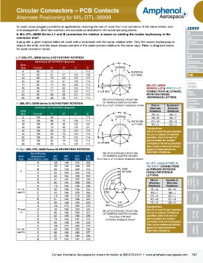
           To avoid cross-plugging problems in applications requiring the use of more than one connector of the same series, size   38999
           and arrange ment, alternate rotations are available as indicated in the accompanying charts.
           In MIL-DTL-38999 Series I, II and III connectors the rotation is based on rotating the master key/keyway in the   III
           connector shell.                                                                                       HD
           A plug with a given rotation letter will mate with a receptacle with the same rotation letter. Only the master key/keyway ro-  Dualok
           tates in the shell, and the insert always remains in the same position relative to the minor keys. Refer to diagrams below   II
           for each connector series.
                                                                                                                  I
                                                                                                                  SJT
           LJT (MIL-DTL-38999 Series I) KEY/KEYWAY ROTATION
                      AB ANGLE OF ROTATION (Degrees)                                                              Accessories
             Shell                                                                                                Aquacon
              Size   Normal°    A°     B°     C°     D°                NORMAL
               9       95       77     –      –      113            B  A   D  C  ROTATION                         Herm/Seal
              11       95       81     67     123    109     AB                 LETTERS                           PCB
              13       95       75     63     127    115
              15       95       74     61     129    116                                                          HigH
              17       95       77     65     125    113                                 MIL-DTL-38999            Speed
              19       95       77     65     125    113                                 SERIES I LJT & SERIES II JT
                                                             ˚
              21       95       77     65     125    113    5  LJT REF                   CONNECTORS ALTERNATE     Fiber
              23       95       80     69     121    110                                 ROTATION CROSS           Optics
              25       95       80     69     121    110                                 -REFERENCE LETTERS
                                                               RELATIVE POSSIBLE POSITION                         Contacts
           JT (MIL-DTL-38999 Series II) KEY/KEYWAY ROTATION    OF ROTATED MASTER KEYWAY                           Connectors
                                                           (front face of LJT connector receptacle shown)  Pins in   Sockets in   Cables
                      AB ANGLE OF ROTATION (Degrees)                                       Alternate   Alternate
             Shell                                                                         Rotations  Rotations
              Size   Normal°    A°     B°     C°     D°                                     PA = E     SA = F
               8       100      82     –      –      118               NORMAL               PB = R     SB = T        Transient  eMi Filter
              10       100      86     72     128    114            B  A   D  C  ROTATION   PC = W     SC = X
              12       100      80     68     132    120     AB                 LETTERS     PD = Y     SD = Z
              14       100      79     66     134    121                                 Explanation:
              16       100      82     70     130    118                                 Use P at end of part number
              18       100      82     70     130    118                                 for pin contacts in Normal    26482
              20       100      82     70     130    118                                 position. Use S at end of   Matrix 2
              22       100      85     74     126    115                                 part number for socket
                                                             ˚
              24       100      85     74     126    115    10  JT REF                   contacts in Normal position.
                                                                                         Use cross-reference letters
           Tri-Start (MIL-DTL-38999 Series III) KEY/KEYWAY ROTATION                      given in chart above for     Matrix|pyle
                                                                                         alternate rotations.          83723 iii
                   Key & Keyway                                RELATIVE POSSIBLE POSITION
            Shell   Arrangement   AR°   BR°   CR°    DR°       OF ROTATED MASTER KEYWAY
            Size  Identification Letter  BSC  BSC  BSC  BSC  (front face of JT connector receptacle shown)
                       N         105    140   215    265                                 MIL-DTL-38999 SERIES III,
                        A        102    132   248    320                                 TRI-START CONNECTORS        pyle    26500
                        B         80    118   230    312                  MAIN           ALTERNATE ROTATION
             9                                                            KEYWAY
                       C          35    140   205    275                                 CROSS-REFERENCE
                       D          64    155   234    304                                 LETTERS
                        E         91    131   197    240            AR ˚                    Pins in   Sockets in
                       N          95    141   208    236            BSC                    Alternate   Alternate   Matrix  Release   Crimp Rear  5015
                        A        113    156   182    292                                   Rotations  Rotations
            11, 13,     B         90    145   195    252        BR ˚                        PA = G    SA = H
            and 15     C          53    156   220    255        BSC                         PB = I     SB = J
                       D         119    146   176    298                                    PC = K     SC = L
                        E         51    141   184    242                                    PD = M    SD = N         Class L    22992
                       N          80    142   196    293         DR ˚   CR ˚                PE = R     SE = T
                        A        135    170   200    310         BSC    BSC              Explanation:
            17 and      B         49    169   200    244                                 Use P at end of part number
             19        C          66    140   200    257       RELATIVE POSSIBLE POSITION   for pin contacts in Normal
                                                               OF ROTATED MASTER KEYWAY
                       D          62    145   180    280           (front face of Tri-Start    position. Use S at end of   Shells  Back-
                        E         79    153   197    272         connector receptacle shown)  part number for socket
                       N          80    142   196    293                                 contacts in Normal position.
                                                                                         Use cross-reference letters
                        A        135    170   200    310                                 given in chart above for
            21, 23,     B         49    169   200    244                                 alternate rotations.        Others  Options
            and 25     C          66    140   200    257
                       D          62    145   180    280
                        E         79    153   197    272


                                Contact Amphenol Aerospace for more information at 800-678-0141  •  www.amphenol-aerospace.com  147
   143   144   145   146   147   148   149   150   151   152   153