
Page 144 - Circular Connector Backshells and Accessories
P. 144
Type C1 Assembly Instructions
Series 38 EMI/RFI Non-Environmental Backshells
38
with Strain Relief
ASSEMBLY INSTRUCTIONS
TYPE C1 HEAVY-DUTY SHIELD TERMINATIONS
Ground Strain
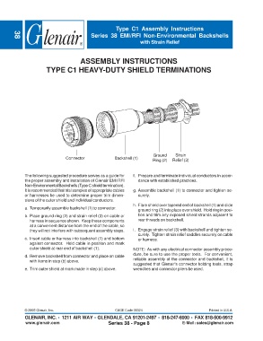
Connector Backshell (1)
Ring (2) Relief (3)
The following suggested procedure serves as a guide for f. Prepare and terminate individual conductors in accor-
the proper assembly and installation of Glenair EMI/RFI dance with established practices.
Non-Environmental Backshells (Type C shield termination).
It is recommended that trial samples of appropriate cables g. Assemble backshell (1) to connector and tighten se-
or harnesses be used to determine proper trim dimen- curely.
sions of the outer shield and individual conductors.
h. Flare shield over tapered end of backshell (1) and slide
a. Temporarily assemble backshell (1) to connector.
ground ring (2) into place over shield. Hold ring in posi-
b. Place ground ring (2) and strain relief (3) on cable or tion and trim any exposed shield strands adjacent to
harness in sequence shown. Keep these components rear threads on backshell.
at a convenient distance from the end of the cable, so
they will not interfere with subsequent assembly steps. i. Engage strain relief (3) with backshell and tighten se-
curely. Tighten strain relief saddles securely on cable
c. Insert cable or harness into backshell (1) and bottom or harness.
against connector. Hold cable in position and mark
outer shield at rear end of backshell (1). NOTE: As with any electrical connector assembly proce-
d. Remove backshell from connector and place on cable dure, be sure to use the proper tools. For convenient,
with items in step (b) above. reliable assembly of the connector and backshell, it is
suggested that Glenair's connector holding tools, strap
e. Trim outer shield at mark made in step (c) above. wrenches and connector pliers be used.
© 2005 Glenair, Inc. CAGE Code 06324 Printed in U.S.A.
GLENAIR, INC. • 1211 AIR WAY • GLENDALE, CA 91201-2497 • 818-247-6000 • FAX 818-500-9912
www.glenair.com Series 38 - Page 8 E-Mail: sales@glenair.com