
Page 148 - Circular Connector Backshells and Accessories
P. 148
Type F Assembly Instructions
Series 38 EMI/RFI Non-Environmental Backshells
38
with Strain Relief
ASSEMBLY INSTRUCTIONS
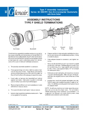
TYPE F SHIELD TERMINATIONS
Ground Ground Strain
Connector Backshell Ring Ring Relief
The following suggested procedure serves as a guide for g. Prepare and terminate contacts to individual conduc-
the proper assembly and installation of Glenair EMI/RFI tors in accordance with established practices. (Crimp
Non-Environmental Backshells (Type F shield termination). or solder in place.)
It is recommended that trial samples of appropriate cables
or harnesses be used to determine proper trim dimen- h. Slide adapter forward to connector, and tighten se-
sions of the outer shield and individual conductors. curely.
i. Move double beveled ground ring forward to pigtail
shield area, fold back individual pigtails evenly over
a. Temporarily assemble backshell to connector. the beveled ring, tie or tape pigtails back onto wire
bundle. (Note: Leave approximately 1/2” inch of slack
b. Place ground rings and strain relief on cable or har- for subsequent step.)
ness in sequence shown. Keep these components
at a convenient distance from the end of the cable, so j. Pull back over-all braid and push forward over beveled
they will not interfere with subsequent assembly steps. ring and individual pigtails. Slide rear ground ring for-
ward into the angled counter bore at the rear of the
c. Insert cable or harness into backshell and bottom adapter.
against connector. Hold cable in position and mark k. Engage strain relief with adapter and tighten securely.
outer shield at rear end of backshell adapter. Tighten strain relief saddles securely on cable or har-
ness, this will then provide good shielding bonding to
d. Remove backshell from connector and place on cable the adapter shell.
with items in step (b) above.
NOTE: As with any electrical connector assembly proce-
e. Trim outer shield at mark made in step (c) above. dure, be sure to use the proper tools. For convenient,
reliable assembly of the connector and backshell, it is
f. Extract shield pigtail from individual conductor’s. Tape suggested that Glenair’s connector holding tools, strap
or tie pigtails to the bundle. wrenches and connector pliers be used.
© 2005 Glenair, Inc. CAGE Code 06324 Printed in U.S.A.
GLENAIR, INC. • 1211 AIR WAY • GLENDALE, CA 91201-2497 • 818-247-6000 • FAX 818-500-9912
www.glenair.com Series 38 - Page 12 E-Mail: sales@glenair.com