
Page 268 - Circular Connector Backshells and Accessories
P. 268
Type A Assembly Instructions
Series 39 EMI/RFI Cable Sealing Backshells
39
with Strain Relief
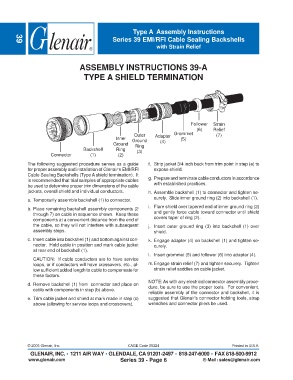
ASSEMBLY INSTRUCTIONS 39-A
TYPE A SHIELD TERMINATION
Follower Strain
(6) Relief
Outer Adapter Grommet (7)
Inner Ground (5)
Ground Ring (4)
Backshell Ring (3)
Connector (1) (2)
The following suggested procedure serves as a guide f. Strip jacket 3/4 inch back from trim point in step (e) to
for proper assembly and installation of Glenair's EMI/RFI expose shield.
Cable Sealing Backshells (Type A shield termination). It
is recommended that trial samples of appropriate cables g. Prepare and terminate cable conductors in accordance
be used to determine proper trim dimensions of the cable with established practices.
jackets, overall shield and individual conductors. h. Assemble backshell (1) to connector and tighten se-
curely. Slide inner ground ring (2) into backshell (1).
a. Temporarily assemble backshell (1) to connector.
i. Flare shield over tapered end of inner ground ring (2)
b. Place remaining backshell assembly components (2
through 7) on cable in sequence shown. Keep these and gently force cable toward connector until shield
components at a convenient distance from the end of covers taper of ring (2).
the cable, so they will not interfere with subsequent j. Insert outer ground ring (3) into backshell (1) over
assembly steps. shield.
c. Insert cable into backshell (1) and bottom against con- k. Engage adapter (4) on backshell (1) and tighten se-
nector. Hold cable in position and mark cable jacket curely.
at rear end of backshell (1).
l. Insert grommet (5) and follower (6) into adapter (4).
CAUTION: If cable conductors are to have service
loops, or if conductors will have crossovers, etc., al- m.Engage strain relief (7) and tighten securely. Tighten
low sufficient added length to cable to compensate for strain relief saddles on cable jacket.
these factors.
NOTE: As with any electrical connector assembly proce-
d. Remove backshell (1) from connector and place on
cable with components in step (b) above. dure, be sure to use the proper tools. For convenient,
reliable assembly of the connector and backshell, it is
e. Trim cable jacket and shield at mark made in step (c) suggested that Glenair's connector holding tools, strap
above (allowing for service loops and crossovers). wrenches and connector pliers be used.
© 2005 Glenair, Inc. CAGE Code 06324 Printed in U.S.A.
GLENAIR, INC. • 1211 AIR WAY • GLENDALE, CA 91201-2497 • 818-247-6000 • FAX 818-500-9912
www.glenair.com Series 39 - Page 6 E-Mail: sales@glenair.com