
Page 273 - Circular Connector Backshells and Accessories
P. 273
Type G Assembly Instructions
Series 39 EMI/RFI Cable Sealing Backshells 39
with Strain Relief
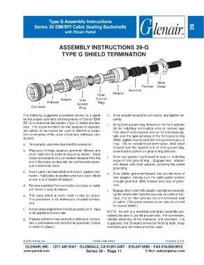
ASSEMBLY INSTRUCTIONS 39-G
TYPE G SHIELD TERMINATION
Strain
Follower Relief
Grommet
Adapter
Outer
Adapter Inner Ground
Follower Ground Ring
Connector Ring
The following suggested procedure serves as a guide h. Slide adapter forward to connector, and tighten se-
for the proper assembly and installation of Glenair EMI/ curely.
RFI Environmental Backshells (Type G shield termina- i. Bring front ground ring forward to the front adapter
tion). It is recommended that trial samples of appropri- (A) for individual termination untie or remove tape
ate cables or harnesses be used to determine proper from step F and disperse evenly the individual pig-
trim dimensions of the outer shield and individual con- tails over the tapered angle of the front ground ring
ductors.
(Note: pigtails may be spot-tied onto groove in ground
a. Temporarily assemble backshell to connector. ring). (B) for overall braid termination, slide braid
forward over the tapered end of front ground ring,
b. Place ground rings, adapters, grommet, follower, and allow braid to bottom on ground ring shoulder.
strain relief on the cable in sequence shown. Keep
these components at a convenient distance from the j. Slide rear ground ring forward to seat on matching
end of the cable, so they will not interfere with subse- angle of front ground ring . Engage rear, adapter
quent assembly steps. and thread onto front adapter, providing the shield
grounding.
c. Insert cable into backshell and bottom against con- k. Slide rubber grommet forward into counter bore of
nector. Hold cable in position and mark outer shield rear adapter, making sure the cable jacket passes
at rear end of backshell adapter.
through grommet, slide follower onto rear of grom-
d. Remove backshell from connector and place on cable met.
with items in step (b) above. l. Engage strain relief with adapter and tighten securely,
e. Trim outer shield at mark made in step (c) above. tighten strain relief saddles securely on cable or har-
This procedure is for individually shielded conduc- ness, this will then provide the environmental seal
tors. on cable. (This same procedure can also be utilized
for overall shield.)
f. Extract shield pigtail from individual conductor’s. Tape
or tie pigtails to the bundle. NOTE: As with any electrical connector assembly pro-
cedure, be sure to use the proper tools. For convenient,
g. Prepare and terminate contacts to individual conduc- reliable assembly of the connector and backshell, it is
tors in accordance with established practices. (Crimp suggested that Glenair’s connector holding tools, strap
or solder in place.) wrenches and connector pliers be used.
© 2005 Glenair, Inc. CAGE Code 06324 Printed in U.S.A.
GLENAIR, INC. • 1211 AIR WAY • GLENDALE, CA 91201-2497 • 818-247-6000 • FAX 818-500-9912
www.glenair.com Series 39 - Page 11 E-Mail: sales@glenair.com