
Page 275 - Circular Connector Backshells and Accessories
P. 275
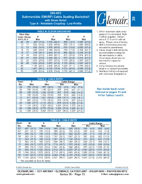
390-001
                    Submersible EMI/RFI Cable Sealing Backshell
                                        with Strain Relief                                                           39
                           Type A - Rotatable Coupling - Low Profile


                                 TABLE III: ELBOW DIMENSIONS                        1. When maximum cable entry
                  Shell Size                                                          (page 21) is exceeded, Style
                Conn. Desig.     E            F            G             H            2 will be supplied.  Dimen-
                 A-F-L-S H      Max          Max          Max           Max           sions E, F, G and H will not
                   08   09    .457  (11.6)    1.760  (44.7)  .500 (12.7)  1.880 (47.8)  apply.  Please consult factory.
                   10   11   .520 (13.2)  1.920 (48.8)  .595 (15.1)  1.990 (50.5)   2. Metric dimensions (mm) are
                   12   13   .582 (14.8)  1.990 (50.5)  .610 (15.5)  2.020 (51.3)     indicated in parentheses.
                   14   15   .645 (16.4)  2.144 (54.5)  .700 (17.8)  2.154 (54.7)   3. Cable range is defined as the
                   16   17   .738 (18.7)  2.254 (57.3)  .885 (22.5)  2.244 (57.0)     accommodations range for
                   18   19   .926 (23.5)  2.444 (62.1)  .975 (24.8)  2.414 (61.3)     the wire bundle or cable.
                   20   21   .926 (23.5)  2.444 (62.1)  .975 (24.8)  2.414 (61.3)     Dimensions shown are not
                   22   23  1.020 (25.9)  2.657 (67.5)  1.125 (28.6)  2.587 (65.7)    intended for inspection
                   24   25  1.020 (25.9)  2.657 (67.5)  1.125 (28.6)  2.587 (65.7)    criteria.
                   28       1.145 (29.1)  2.690 (68.3)  1.225 (31.1)  2.740 (69.6)  4. Consult factory for shorter
                   32       1.207 (30.7)  2.790 (70.9)  1.575 (40.0)  2.990 (75.9)    lengths on straight backshells.
                   36       1.238 (31.4)  2.930 (74.4)  1.775 (45.1)  3.040 (77.2)  5. Interface O-Ring not supplied
                                                                                      with connector designator A.

                                 TABLE X: CABLE ENTRY
                 Dash       T            V            Cable Range
                 No.      Max           Max          Min         Max
                  04    .780 (19.8)  .957 (24.3)  .125  (3.2)  .312  (7.9)
                  06    .780 (19.8)  1.145 (29.1)  .250  (6.4)  .437 (11.1)          See inside back cover
                  08    .780 (19.8)  1.332 (33.8)  .387  (9.8)  .562 (14.3)        fold-out or pages 13 and
                  10    .780 (19.8)  1.332 (33.8)  .350  (8.9)  .625 (15.9)          14 for Tables I and II.
                  12    .811 (20.6)  1.551 (39.4)  .500 (12.7)  .750 (19.1)
                  16    .905 (23.0)  1.770 (45.0)  .625 (15.9)  .937 (23.8)
                  20   1.092 (27.7)  2.113 (53.7)  .875 (22.2) 1.250 (31.8)
                  24   1.124 (28.5)  2.363 (60.0)  1.000 (25.4) 1.375 (34.9)
                  28   1.399 (35.5)  2.770 (70.4)  1.250 (31.8) 1.625 (41.3)
                  32   1.399 (35.5)  3.020 (76.7)  1.437 (36.5) 1.875 (47.6)


                                             TABLE XI: CABLE ENTRY
                Dash      W           X            Y            Z             Cable Range
                No.      Max         Max          Max          Max         Min          Max
                03*   .437 (11.1)  .760 (19.3)  .843 (21.4)  .630 (16.0)  .156  (4.0)  .250  (6.4)
                04*   .437 (11.1)  .760 (19.3)  .906 (23.0)  .755 (19.2)  .188  (4.8)  .312  (7.9)
                06*   .500 (12.7)  .760 (19.3) 1.093 (27.8)  .942 (23.9)  .281  (7.1)  .438 (11.1)
                 08   .563 (14.3)  .760 (19.3) 1.187 (30.1)  1.067 (27.1)  .387  (9.8)  .562 (14.3)
                 10   .563 (14.3)  .760 (19.3) 1.281 (32.5)  1.192 (30.3)  .375  (9.5)  .625 (15.9)
                 12   .563 (14.3)  .760 (19.3) 1.500 (38.1)  1.380 (35.1)  .438 (11.1)  .750 (19.1)
                 16   .656 (16.7)  1.073 (27.3) 1.719 (43.7)  1.535 (39.0)  .625 (15.9)  .938 (23.8)
                 20   .656 (16.7)  1.323 (33.6) 2.062 (52.4)  1.848 (46.9)  .875 (22.2)  1.250 (31.8)
                 24   .656 (16.7)  1.323 (33.6) 2.312 (58.7)  2.255 (57.3) 1.000 (25.4)  1.375 (34.9)
                 28  1.188 (30.2)  1.572 (39.9) 2.719 (69.1)  2.505 (63.6) 1.250 (31.8)  1.625 (41.3)
                32* 1.187 (30.1)  1.572 (39.9) 2.969 (75.4)  2.755 (70.0) 1.437 (36.5)  1.875 (47.6)
                40* 1.125 (28.6)  1.572 (39.9) 3.531 (89.7)  3.255 (82.7) 1.875 (47.6)  2.375 (60.3)
                 *  Not available in Style M clamp.

               © 2005 Glenair, Inc.                      CAGE Code 06324                            Printed in U.S.A.
                GLENAIR, INC. • 1211 AIR WAY • GLENDALE, CA 91201-2497 • 818-247-6000 • FAX 818-500-9912
               www.glenair.com                       Series 39 -  Page 13               E-Mail: sales@glenair.com