
Page 93 - Circular Connector Backshells and Accessories
P. 93
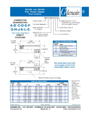
330-003 and 330-004
                                   Pipe Thread  Adapter                                                              33
                                        Direct Coupling


                                                              330 F S 003 N 16 03-5
                    CONNECTOR                 Product Series                        Length Designator (1/2 inch
                   DESIGNATORS                                                        increments: e.g. 5=2.5 inches,
               A-B -C-D-E-F                   Connector Designator                    Minimum Lengths Table III)
                       *
                                              Angle and Profile                     Cable Entry (Table III)
                G-H-J-K-L-S                      S = Straight
                                                                                    Shell Size (Table I)
                * Conn. Desig. B See Note 3   Basic Part No.
                        DIRECT                   003 = External Thread              Finish (Table II)
                                                 004 = Internal Thread
                      COUPLING

                A Thread                 Length                             TABLE II: STANDARD FINISHES
                (Table I)             ± .060 (1.52)
                                                                           GLENAIR
                                                                           SYMBOL  FINISH
                                                                              B    Cadmium Plate, Olive Drab
                                                                              C    Anodize, Black
                      B                                                      G     Hard Coat, Anodic
                   (Table I)                              F (Table III)      M     Electroless Nickel
                                                                             NF    Cadmium Plate, Olive Drab Over
                                                                                     Electroless Nickel
                                                                          See Back Cover for Complete Finish Information
                                                                                  and Additional Finish Options
                                                    E
                                                 (Table III)  External
                                                              Tapered
                                        Length                Pipe
               A Thread               ± .060 (1.52)           Thread        See inside back cover fold-
               (Table I)                           E                        out or pages 13 and 14 for
                                                (Table III)
                                                                            unabridged Tables I and II.

                     B
                   (Table I)                            G (Table III)


                                                      Wrench Flats Typ. (Space Permitting)

                                            TABLE III: CABLE ENTRY                               1. Pipe threads per
                Dash     Pipe                                                      Length           American
                                                                                                    standard taper
                 No.    Thread        E            F Dia         G Dia          Min     Desig.      pipe thread.
                  01     1/8      .391  (9.9)    .405 (10.3)   .500 (12.7)   2.0 (50.8)   4      2. Metric dimensions
                  02     1/4      .593 (15.1)    .540 (13.7)   .625 (15.9)   2.0 (50.8)   4         (mm) are
                  03     3/8      .593 (15.1)    .675 (17.1)   .875 (22.2)   2.0 (50.8)   4         indicated in
                                                                                                    parentheses.
                  04     1/2      .781 (19.8)    .840 (21.3)  1.000 (25.4)   2.5 (63.5)   5      3. When using
                  05     3/4      .812 (20.6)   1.050 (26.7)  1.250 (31.8)   2.5 (63.5)   5         Connector
                  06      1      1.000 (25.4)   1.315 (33.4)  1.500 (38.1)   2.5 (63.5)   5         Designator B
                                                                                                    refer to pages 18
                  07     1 1/4   1.031 (26.2)   1.660 (42.2)  1.750 (44.5)   3.0 (76.2)   6         and 19 for part
                  08     1 1/2   1.031 (26.2)   1.900 (48.3)  2.125 (54.0)   3.0 (76.2)   6         number develop-
                  09      2      1.062 (27.0)   2.375 (60.3)  2.500 (63.5)   3.0 (76.2)   6         ment.
                  10     2 1/2   1.453 (36.9)   2.875 (73.0)  3.250 (82.6)   3.0 (76.2)   6


               © 2005 Glenair, Inc.                      CAGE Code 06324                             Printed in U.S.A.
               GLENAIR, INC. • 1211 AIR WAY • GLENDALE, CA 91201-2497 • 818-247-6000 • FAX 818-500-9912
               www.glenair.com                           Series 33 - 3                  E-Mail: sales@glenair.com