
Page 97 - Circular Connector Backshells and Accessories
P. 97
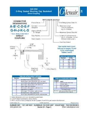
340-002
                       O-Ring Sealed Shorting Cap Backshell                                                          34
                                        Direct Coupling


                                                             340 F S 002 M 16-5 H 6 A
                    CONNECTOR
                   DESIGNATORS               Product Series                          End Fitting Symbol (Table IV)
               A-B -C-D-E-F                  Connector                               Attachment Length
                       *
                                                                                       (1/2 inch increments:
                                             Designator
                G-H-J-K-L-S                  Angle and Profile                         e.g. 6 = 3 inches)
                                                S = Straight                         Attachment Symbol (Table III)
                * Conn. Desig. B See Note 3
                        DIRECT               Basic Part No.                          Length (1/2 inch increments:
                      COUPLING               Finish (Table II)                         e.g. 5 = 2.5 inches, 1.0 Inch
                                                                                       Minimum Order Length )
                                                                                     Shell Size (Table I)
                                           Length
                                         ± .060 (1.52)
               A Thread                O-Ring                                      See inside back cover
                (Table I)                                                         fold-out or pages 13 and
                                                                                     14 for unabrdiged
                                                                                        Tables I and II.
                      B
                    (Table I)
                                                                                      TABLE IV: END FITTING
                                                                                       Symbol     E Dia.
                                                                                         A      .140  (3.6)
                                                                                         B      .167  (4.2)
                                                                .50 (12.7)               C      .182  (4.6)
                                                                  Max                    D      .191  (4.9)
                                                                                         E      .125  (3.2)
                                                                                          F     .218  (5.5)
                                             Attachment            E Dia (Table IV)
                                             Length ±.25
                                                (6.4)


                             TABLE III: ATTACHMENT OPTIONS
                     Symbol                 Attachment                         TABLE II: STANDARD FINISHES
                        C      No attachment, body strap only                GLENAIR
                        D      Bead chain, cres, passivate, with terminal    SYMBOL   FINISH
                        E      Link chain, cres, passivate, with reverse link   B     Cadmium Plate, Olive Drab
                        F      Wire rope, nylon jacket, with terminal           C     Anodize, Black
                        G      Nylon rope, with terminal                        G     Hard Coat, Anodic
                                                                                      Electroless Nickel
                                                                                M
                        H      Wire rope, teflon jacket, with terminal          NF    Cadmium Plate, Olive Drab Over
                        N      Attachment omitted                                       Electroless Nickel
                        R      Wire rope, PVC jacket, with terminal          See Back Cover for Complete Finish Information
                        S      #8 Sash chain, cres, passivate                       and Additional Finish Options
                        U      Wire rope, polyurethane jacket, with terminal
               1. Metric dimensions (mm) are indicated in parentheses.
               2. Custom engraving available, consult factory.
               3. When using Connector Designator B refer to pages 18 and 19 for part number development.

               © 2005 Glenair, Inc.                      CAGE Code 06324                             Printed in U.S.A.
               GLENAIR, INC. • 1211 AIR WAY • GLENDALE, CA 91201-2497 • 818-247-6000 • FAX 818-500-9912
               www.glenair.com                        Series 34 - Page 3                E-Mail: sales@glenair.com