
Page 102 - Circular Connector Backshells and Accessories
P. 102
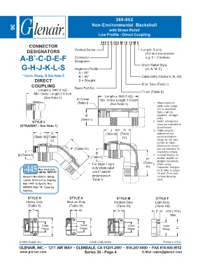
360-002
                                                        Non-Environmental  Backshell
                                                                  with Strain Relief
       36
                                                            Low Profile - Direct Coupling

                                                             360 F S 002 M 16 10 M 6
                  CONNECTOR
                 DESIGNATORS                  Product Series                          Length: S only
                                                                                        (1/2 inch increments:
             A-B -C-D-E-F                     Connector                                 e.g. 6 = 3 inches)
                     *
                                              Designator
              G-H-J-K-L-S                     Angle and Profile                       Strain Relief Style
                                                                                        (H, A, M, F)
                                                A = 90°
              * Conn. Desig. B See Note 5       B = 45°                               Cable Entry (Tables X, XI, XII)
                      DIRECT                    S = Straight
                    COUPLING                  Basic Part No.                          Shell Size (Table I)
                        Length ± .060 (1.52)
                     Min. Order Length 2.0 Inch                                       Finish (Table II)
                                                                Length ± .060 (1.52)
                           (See Note 4)        A Thread      Min. Order Length 1.5 Inch
                                               (Table I)           (See Note 4)              1. When maximum
                                                                                               cable entry (page
                                                                                               22) is exceeded,
                                                                                               Style 2 will be
                                                    B                                          supplied.  (straight
                                                 (Table I)                                     only.)
                    STYLE 2                                                                  2. Metric dimensions
             (STRAIGHT - See Note 1)                                                           (mm) are indicated in
                                                                                               parentheses.
                                                                   J       G                 3. Cable range is
                         J      E                               (Table III)  (Table            defined as the
                     (Table III) (Table                                   IV)                  accommodations
                               IV)                                                             range for the wire
                                                                                               bundle or cable.
                                                                                               Dimensions shown
                                           F* (Table IV)                                       are not intended for
                                                          B                                    inspection criteria.
            B (Table I)                                                                      4. Consult factory for
                                                       (Table I)
                                                                                        H*     shorter lengths on
                                                                                               straight backshells.
                                                      * For Style F light              (Table  5. When using
                                                        duty strain relief              IV)    Connector Designa-
                        Now Available                                                          tor B refer to pages
                                                             1
                         with the “NESTOR”              use F  and H 1                         18 and 19 for part
               Glenair’s Non-Detent,  Spring-           dimensions in                          number develop-
               Loaded,  Self-Locking Coupling.          Table V.                               ment.
               Add “-445” to Specify This
               AS85049 Style “N” Coupling
               Interface.

                  STYLE H                  STYLE A                     STYLE M                STYLE F
                 Heavy Duty              Medium Duty                 Medium Duty              Light Duty
                  (Table X)               (Table XI)                   (Table XI)             (Table XII)
                    T                           W                      X                      Z     .416 (10.5)
                                                                                                      Max


                          Cable  V               Cable  Y                     Cable  Y            Cable
                          Range                  Range                       Range                Range   Z


             © 2005 Glenair, Inc.                      CAGE Code 06324                            Printed in U.S.A.
             GLENAIR, INC. • 1211 AIR WAY • GLENDALE, CA 91201-2497 • 818-247-6000 • FAX 818-500-9912
             www.glenair.com                       Series 36 - Page 4                 E-Mail: sales@glenair.com