
Page 105 - Circular Connector Backshells and Accessories
P. 105
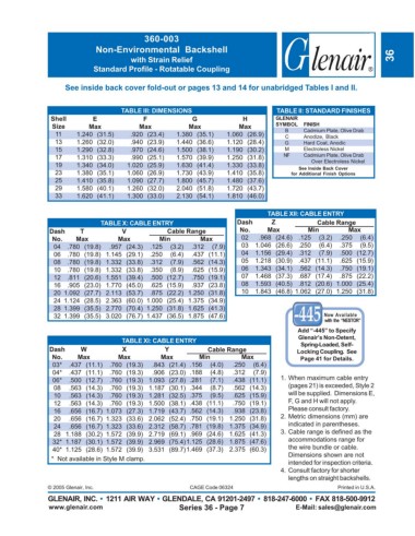
360-003
                             Non-Environmental Backshell
                                        with Strain Relief                                                           36
                            Standard Profile - Rotatable Coupling

                    See inside back cover fold-out or pages 13 and 14 for unabridged Tables I and II.


                                     TABLE III: DIMENSIONS                         TABLE II: STANDARD FINISHES
                Shell       E              F              G              H        GLENAIR
                Size       Max            Max            Max           Max        SYMBOL   FINISH
                 11     1.240 (31.5)   .920 (23.4)   1.380 (35.1)   1.060 (26.9)     B     Cadmium Plate, Olive Drab
                                                                                     C
                                                                                           Anodize, Black
                 13     1.260 (32.0)   .940 (23.9)   1.440 (36.6)   1.120 (28.4)     G     Hard Coat, Anodic
                 15     1.290 (32.8)   .970 (24.6)   1.500 (38.1)   1.190 (30.2)     M     Electroless Nickel
                 17     1.310 (33.3)   .990 (25.1)   1.570 (39.9)   1.250 (31.8)     NF    Cadmium Plate, Olive Drab
                                                                                             Over Electroless Nickel
                 19     1.340 (34.0)  1.020 (25.9)   1.630 (41.4)   1.330 (33.8)         See Inside Back Cover
                 23     1.380 (35.1)  1.060 (26.9)   1.730 (43.9)   1.410 (35.8)       for Additional Finish Options
                 25     1.410 (35.8)  1.090 (27.7)   1.800 (45.7)   1.480 (37.6)
                 29     1.580 (40.1)  1.260 (32.0)   2.040 (51.8)   1.720 (43.7)
                 33     1.620 (41.1)  1.300 (33.0)   2.130 (54.1)   1.810 (46.0)

                                                                                TABLE XII: CABLE ENTRY
                               TABLE X: CABLE ENTRY                    Dash      Z             Cable Range
               Dash      T           V            Cable Range           No.     Max         Min         Max
                No.    Max          Max         Min         Max         02   .968 (24.6)  .125  (3.2)  .250  (6.4)
                 04  .780 (19.8)  .957 (24.3)  .125  (3.2)  .312  (7.9)  03  1.046 (26.6)  .250  (6.4)  .375  (9.5)
                 06  .780 (19.8) 1.145 (29.1)  .250  (6.4)  .437 (11.1)  04  1.156 (29.4)  .312  (7.9)  .500 (12.7)
                 08  .780 (19.8) 1.332 (33.8)  .312  (7.9)  .562 (14.3)  05  1.218 (30.9)  .437 (11.1)  .625 (15.9)
                 10  .780 (19.8) 1.332 (33.8)  .350  (8.9)  .625 (15.9)  06  1.343 (34.1)  .562 (14.3)  .750 (19.1)
                 12  .811 (20.6) 1.551 (39.4)  .500 (12.7)  .750 (19.1)  07  1.468 (37.3)  .687 (17.4)  .875 (22.2)
                 16  .905 (23.0) 1.770 (45.0)  .625 (15.9)  .937 (23.8)  08  1.593 (40.5)  .812 (20.6) 1.000 (25.4)
                 20 1.092 (27.7) 2.113 (53.7)  .875 (22.2)  1.250 (31.8)  10  1.843 (46.8)  1.062 (27.0) 1.250 (31.8)
                 24 1.124 (28.5) 2.363 (60.0)  1.000 (25.4)  1.375 (34.9)
                 28 1.399 (35.5) 2.770 (70.4)  1.250 (31.8)  1.625 (41.3)
                 32 1.399 (35.5) 3.020 (76.7)  1.437 (36.5)  1.875 (47.6)                        Now Available
                                                                                                 with the “NESTOR”
                                                                                         Add “-445” to Specify
                                     TABLE XI: CABLE ENTRY                               Glenair’s Non-Detent,
                                                                                          Spring-Loaded, Self-
               Dash      W           X            Y           Cable Range                Locking Coupling.  See
                No.     Max         Max         Max         Min         Max               Page 41 for Details.
                03*  .437 (11.1)  .760 (19.3)  .843 (21.4)  .156  (4.0)  .250  (6.4)
                04*  .437 (11.1)  .760 (19.3)  .906 (23.0)  .188  (4.8)  .312  (7.9)
                06*  .500 (12.7)  .760 (19.3) 1.093 (27.8)  .281  (7.1)  .438 (11.1)  1. When maximum cable entry
                 08  .563 (14.3)  .760 (19.3) 1.187 (30.1)  .344  (8.7)  .562 (14.3)  (pages 21) is exceeded, Style 2
                 10  .563 (14.3)  .760 (19.3) 1.281 (32.5)  .375  (9.5)  .625 (15.9)  will be supplied.  Dimensions E,
                 12  .563 (14.3)  .760 (19.3) 1.500 (38.1)  .438 (11.1)  .750 (19.1)  F, G and H will not apply.
                 16  .656 (16.7)  1.073 (27.3) 1.719 (43.7)  .562 (14.3)  .938 (23.8)  Please consult factory.
                 20  .656 (16.7)  1.323 (33.6) 2.062 (52.4)  .750 (19.1)  1.250 (31.8)  2. Metric dimensions (mm) are
                 24  .656 (16.7)  1.323 (33.6) 2.312 (58.7)  .781 (19.8)  1.375 (34.9)  indicated in parentheses.
                 28 1.188 (30.2)  1.572 (39.9) 2.719 (69.1)  .969 (24.6)  1.625 (41.3)  3. Cable range is defined as the
                32* 1.187 (30.1)  1.572 (39.9) 2.969 (75.4) 1.125 (28.6)  1.875 (47.6)  accommodations range for
                40* 1.125 (28.6)  1.572 (39.9) 3.531 (89.7) 1.469 (37.3)  2.375 (60.3)  the wire bundle or cable.
                *  Not available in Style M clamp.                                    Dimensions shown are not
                                                                                      intended for inspection criteria.
                                                                                    4. Consult factory for shorter
                                                                                      lengths on straight backshells.
               © 2005 Glenair, Inc.                      CAGE Code 06324                             Printed in U.S.A.
               GLENAIR, INC. • 1211 AIR WAY • GLENDALE, CA 91201-2497 • 818-247-6000 • FAX 818-500-9912
               www.glenair.com                        Series 36 - Page 7                E-Mail: sales@glenair.com