
Page 254 - Circular Connector Backshells and Accessories
P. 254
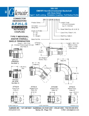
380-105
                                                   EMI/RFI Non-Environmental Backshell
                                                                  with Strain Relief
        38
                                          Type F - Self-Locking - Rotatable Coupling - Full Radius Profile

                   CONNECTOR                                380 F S 105 M 16 08 A 6
                  DESIGNATORS
                 A-F-H-L-S                  Product Series                          Length: S only
                                                                                       (1/2 inch increments:
                                            Connector                                  e.g. 6 = 3 inches)
                  SELF-LOCKING              Designator
                    ROTATABLE                                                       Strain Relief Style (H, A, M, D)
                     COUPLING               Angle and Profile
                                               M = 45°                              Cable Entry (Table X, XI)
                                               N = 90°
               TYPE F INDIVIDUAL               S = Straight                         Shell Size (Table I)
                AND/OR OVERALL              Basic Part No.                          Finish (Table II)
              SHIELD TERMINATION
                          Length ± .060 (1.52)   A Thread                                    Length ± .060 (1.52)
                     Minimum Order Length 2.0 Inch  (Table I)                                  Minimum Order
                             (See Note 4)                                                      Length 1.5 Inch
                                                                                                (See Note 4)
                                                       E Typ.
                                                      (Table I)


                                                       Anti-Rotation
                                                                                       H
                  STYLE 2                              Device (Typ.)
                 (STRAIGHT                                                          (Table III)
                 See Note 1)                      F
                                              (Table III)
                            1.00 (25.4)
                               Max                            G (Table III)


                                                                                                    J (Table III)


                  STYLE 2
                  (45° & 90°
                 See Note 1)

                   STYLE H                  STYLE A                     STYLE M                 STYLE D
                  Heavy Duty              Medium Duty                 Medium Duty              Medium Duty
                   (Table X)                (Table XI)                  (Table XI)              (Table XI)
                      T                          W                      X                            .135 (3.4)
                                                                                                       Max


                           Cable                  Cable                        Cable                 Cable
                           Range  V               Range  Y                    Range  Y               Entry  Z


             © 2005 Glenair, Inc.                      CAGE Code 06324                            Printed in U.S.A.
             GLENAIR, INC. • 1211 AIR WAY • GLENDALE, CA 91201-2497 • 818-247-6000 • FAX 818-500-9912
             www.glenair.com                      Series 38 - Page 118                E-Mail: sales@glenair.com