
Page 185 - Circular Connector Backshells and Accessories
P. 185
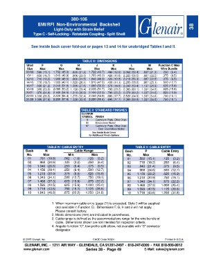
380-106
                        EMI/RFI Non-Environmental Backshell
                                  Light-Duty with Strain Relief                                                       38
                     Type C - Self-Locking -  Rotatable Coupling - Split Shell


                    See inside back cover fold-out or pages 13 and 14 for unabridged Tables I and II.


                                                   TABLE III: DIMENSIONS
                 Shell    F          G          H          J         K          L          M     Function C Max
                 Size    Max        Max        Max        Max       Max        Max        Max     Wire Bundle
                 08/09  .596 (15.1)  1.782 (45.3)  .836 (21.2)  1.722 (43.7)  .496 (12.6) 2.062 (52.4)  .837 (21.3)  .250 (6.4)
                 10/11  .656 (16.7)  1.845 (46.9)  .906 (23.0)  1.785 (45.3)  .426 (10.8) 2.225 (56.5)  .887 (22.5)  .375 (9.5)
                 12/13  .716 (18.2)  1.908 (48.5)  .966 (24.5)  1.848 (46.9)  .426 (10.8) 2.218 (56.3)  .887 (22.5)  .375 (9.5)
                 14/15  .776 (19.7)  1.935 (49.1)  1.026 (26.1)  1.875 (47.6)  .436 (11.1) 2.285 (58.0)  .987 (25.1)  .500 (12.7)
                 16/17  .836 (21.2)  2.040 (51.8)  1.086 (27.6)  1.980 (50.3)  .576 (14.6) 2.340 (59.4)  1.137 (28.9)  .625 (15.9)
                 18/19  .906 (23.0)  2.095 (53.2)  1.156 (29.4)  2.035 (51.7)  .796 (20.2) 2.365 (60.1)  1.337 (34.0)  .625 (15.9)
                 20/21  .976 (24.8)  2.160 (54.9)  1.216 (30.9)  2.100 (53.3)  .796 (20.2) 2.370 (60.2)  1.337 (34.0)  .625 (15.9)
                 22/23  1.036 (26.3)  2.220 (56.4)  1.276 (32.4)  2.160 (54.9)  .696 (17.7) 2.520 (64.0)  1.337 (34.0)  .750 (19.1)
                 24/25  1.096 (27.8)  2.280 (57.9)  1.336 (33.9)  2.220 (56.4)  .696 (17.7) 2.360 (59.9)  1.337 (34.0)  .750 (19.1)


                                                  TABLE II: STANDARD FINISHES
                                                  GLENAIR
                                                  SYMBOL   FINISH
                                                     B     Cadmium Plate, Olive Drab
                                                     M     Electroless Nickel
                                                     NF    Cadmium Plate, Olive Drab
                                                               Over Electroless Nickel
                                                         See Inside Back Cover
                                                       for Additional Finish Options


                             TABLE IV: CABLE ENTRY                                 TABLE V: CABLE ENTRY
                 Dash       N                 Cable Range                    Dash        P        Cable Entry
                 No.       Max            Min           Max                  No.       Max            Max
                  01     .781 (19.8)   .062  (1.6)    .125  (3.2)             01     .593 (15.1)   .125  (3.2)
                  02     .968 (24.6)   .125  (3.2)    .250  (6.4)             02     .718 (18.2)   .250  (6.4)
                  03    1.046 (26.6)   .250  (6.4)    .375  (9.5)             03     .843 (21.4)   .375  (9.5)
                  04    1.156 (29.4)   .250  (6.4)    .500 (12.7)             04     .968 (24.6)   .500 (12.7)
                  05    1.218 (30.9)   .375  (9.5)    .625 (15.9)             05    1.109 (28.2)   .625 (15.9)
                  06    1.343 (34.1)   .500 (12.7)    .750 (19.1)             06    1.218 (30.9)   .750 (19.1)
                  07    1.468 (37.3)   .625 (15.9)    .875 (22.2)             07    1.343 (34.1)   .875 (22.2)
                  08    1.593 (40.5)   .625 (15.9)   1.000 (25.4)             08    1.468 (37.3)  1.000 (25.4)
                  09    1.718 (43.6)   .750 (19.1)   1.125 (28.6)             09    1.593 (40.5)  1.125 (28.6)
                  10    1.843 (46.8)   .875 (22.2)   1.250 (31.8)             10    1.718 (43.6)  1.250 (31.8)


                                1. When maximum cable entry (page 21) is exceeded, Style 2 will be supplied
                                   (not available in Function C).  Dimensions F, G, H and J will not apply.
                                   Please consult factory.
                                2. Metric dimensions (mm) are indicated in parentheses.
                                3. Cable range is defined as the accommodations range for the wire bundle or
                                   cable.  Dimensions shown are not intended for inspection criteria.
                                4. Angular function "C", low-profile split elbow, not available with "S" connector
                                   designator.


               © 2005 Glenair, Inc.                      CAGE Code 06324                             Printed in U.S.A.
                GLENAIR, INC. • 1211 AIR WAY •   GLENDALE, CA 91201-2497 •    818-247-6000 •  FAX 818-500-9912
               www.glenair.com                       Series 38 -  Page 49               E-Mail: sales@glenair.com