
Page 23 - Circular Connector Backshells and Accessories
P. 23
Style 1/Style 2 Backshells
General Information and How to Order
Rotatable Coupling "X" Diameters
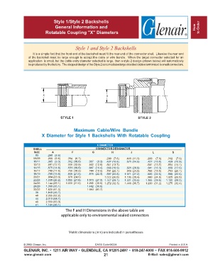
Style 1 and Style 2 Backshells
It is a simple fact that the front end of the backshell must fit the rear end of the connector shell. Likewise the rear end
of the backshell must be large enough to accept the cable or wire bundle. When the target connector selected for an
application is small, but the cable entry diameter selected is large, then a style 2 design (shown below) will automatically
be produced by the factory. The stepped design of the Style 2 accomodates large shielded cables terminated to small connectors.
X X
STYLE 1 STYLE 2
Maximum Cable/Wire Bundle
X Diameter for Style 1 Backshells With Rotatable Coupling
X DIAMETER
SHELL CONNECTOR DESIGNATOR
SIZE A F G H J L S
03 .260 (6.6)
08/09 .260 (6.6) .264 (6.7) .299 (7.6) .446 (11.3) .299 (7.6) .312 (7.9)
10/11 .365 (9.3) .392 (10.0) .367 (9.3) .427 (10.8) .571 (14.5) .427 (10.8) .429 (10.9)
12/13 .501 (12.7) .506 (12.9) .502 (12.8) .541 (13.7) .541 (13.7) .554 (14.1)
14/15 .575 (14.6) .631 (16.0) .647 (16.4) .666 (16.9) .821 (20.9) .641 (16.3) .668 (17.0)
16/17 .700 (17.8) .756 (19.2) .744 (18.9) .791 (20.1) .946 (24.0) .766 (19.5) .793 (20.1)
18/19 .780 (19.8) .845 (21.5) .876 (22.3) .897 (22.8) 1.071 (27.2) .885 (22.5) .888 (22.6)
20/21 .904 (23.0) .970 (24.6) 1.022 (26.0) 1.196 (30.4) .980 (24.9) 1.025 (26.0)
22/23 1.030 (26.2) 1.095 (27.8) 1.073 (27.3) 1.147 (29.1) 1.321 (33.6) 1.165 (29.6) 1.150 (29.2)
24/25 1.144 (29.1) 1.220 (31.0) 1.205 (30.6) 1.272 (32.3) 1.446 (36.7) 1.230 (31.2) 1.275 (32.4)
28/29 1.380 (35.1) 1.442 (36.6)
32/33 1.625 (41.3) 1.640 (41.7)
36 1.840 (46.7)
40 2.055 (52.2)
44 2.310 (58.7)
48 2.560 (65.0)
61 1.184 (30.1)
The F and H Dimensions in the above table are
applicable only to environmental sealed connectors
Metric dimensions (mm) are indicated in parentheses
© 2005 Glenair, Inc. CAGE Code 06324 Printed in U.S.A.
GLENAIR, INC. • 1211 AIR WAY • GLENDALE, CA 91201-2497 • 818-247-6000 • FAX 818-500-9912
www.glenair.com 21 E-Mail: sales@glenair.com