
Page 283 - Circular Connector Backshells and Accessories
P. 283
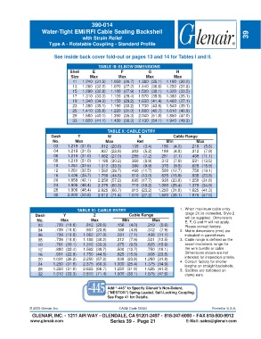
390-014
                     Water-Tight EMI/RFI Cable Sealing Backshell
                                        with Strain Relief                                                           39
                        Type A - Rotatable Coupling - Standard Profile


                          See inside back cover fold-out or pages 13 and 14 for Tables I and II.

                                               TABLE III: ELBOW DIMENSIONS
                                  Shell     E             F            G            H
                                  Size     Max           Max          Max          Max
                                   11   1.240 (31.5)  1.050 (26.7)  1.380 (35.1)  1.190 (30.2)
                                   13   1.260 (32.0)  1.070 (27.2)  1.440 (36.6)  1.250 (31.8)
                                   15   1.290 (32.8)  1.100 (27.9)  1.500 (38.1)  1.320 (33.5)
                                   17   1.310 (33.3)  1.120 (28.4)  1.570 (39.9)  1.380 (35.1)
                                   19   1.340 (34.0)  1.150 (29.2)  1.630 (41.4)  1.460 (37.1)
                                   23   1.380 (35.1)  1.190 (30.2)  1.730 (43.9)  1.540 (39.1)
                                   25   1.410 (35.8)  1.220 (31.0)  1.800 (45.7)  1.610 (40.9)
                                   29   1.580 (40.1)  1.390 (35.3)  2.040 (51.8)  1.850 (47.0)
                                   33   1.620 (41.1)  1.430 (36.3)  2.130 (54.1)  1.940 (49.3)


                                                   TABLE X: CABLE ENTRY
                         Dash         T             W             X               Cable Range
                          No.       Max            Max           Ref           Min           Max
                          03     1.219 (31.0)   .812 (20.6)   .135  (3.4)   .156  (4.0)    .219  (5.6)
                          04     1.219 (31.0)   .937 (23.8)   .203  (5.2)   .188  (4.8)    .312  (7.9)
                          06     1.219 (31.0)  1.062 (27.0)   .285  (7.2)   .281  (7.1)    .438 (11.1)
                          08     1.219 (31.0)  1.188 (30.2)   .350  (8.9)   .312  (7.9)    .531 (13.5)
                          10     1.281 (32.5)  1.312 (33.3)   .390  (9.9)   .375  (9.5)    .625 (15.9)
                          12     1.281 (32.5)  1.562 (39.7)   .460 (11.7)   .500 (12.7)    .750 (19.1)
                          16     1.406 (35.7)  1.750 (44.5)   .510 (13.0)   .625 (15.9)    .938 (23.8)
                          20     1.656 (42.1)  2.250 (57.2)   .695 (17.7)   .938 (23.8)   1.250 (31.8)
                          24     1.906 (48.4)  2.375 (60.3)   .715 (18.2)  1.000 (25.4)   1.375 (34.9)
                          28     1.906 (48.4)  2.625 (66.7)   .915 (23.2)  1.250 (31.8)   1.625 (41.3)
                          32     2.000 (50.8)  2.812 (71.4)  1.070 (27.2)  1.500 (38.1)   1.875 (47.6)


                                     TABLE XI: CABLE ENTRY                           1. When maximum cable entry
                  Dash         Y             Z                Cable Range               (page 21) is exceeded, Style 2
                  No.        Max            Max           Min           Max             will be supplied.  Dimensions
                                                                                        E, F, G and H will not apply.
                   03      .739 (18.8)   .812 (20.6)    .156  (4.0)   .219  (5.6)       Please consult factory.
                   04      .739 (18.8)   .937 (23.8)    .188  (4.8)   .312  (7.9)    2. Metric dimensions (mm) are
                   06      .739 (18.8)  1.062 (27.0)    .281  (7.1)   .438 (11.1)       indicated in parentheses.
                   08      .739 (18.8)  1.188 (30.2)    .312  (7.9)   .531 (13.5)    3. Cable range is defined as the
                   10      .791 (20.1)  1.312 (33.3)    .375  (9.5)   .625 (15.9)       accommodations range for
                   12      .880 (22.4)  1.562 (39.7)    .500 (12.7)   .750 (19.1)       the wire bundle or cable.
                   16      .901 (22.9)  1.750 (44.5)    .625 (15.9)   .938 (23.8)       Dimensions shown are not
                                                                                        intended for inspection criteria.
                   20     1.031 (26.2)  2.250 (57.2)    .938 (23.8)  1.250 (31.8)    4. Consult factory for shorter
                   24     1.250 (31.8)  2.375 (60.3)   1.000 (25.4)  1.375 (34.9)       lengths on straight backshells.
                   28     1.250 (31.8)  2.625 (66.7)   1.250 (31.8)  1.625 (41.3)    5. Saddles are bottomed on
                   32     1.312 (33.3)  2.812 (71.4)   1.500 (38.1)  1.875 (47.6)       clamp ears.


                                                   Add “-445” to Specify Glenair’s Non-Detent,
                                                   ("NESTOR") Spring-Loaded, Self-Locking Coupling.
                                                   See Page 41 for Details.


               © 2005 Glenair, Inc.                      CAGE Code 06324                            Printed in U.S.A.
                GLENAIR, INC. • 1211 AIR WAY • GLENDALE, CA 91201-2497 • 818-247-6000 • FAX 818-500-9912
               www.glenair.com                       Series 39 -  Page 21               E-Mail: sales@glenair.com