
Page 111 - Circular Connector Backshells and Accessories
P. 111
Series 37
Cable Sealing Backshells 37
Assembly Instructions
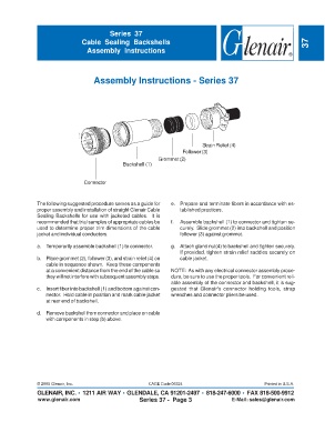
Assembly Instructions - Series 37
Strain Relief (4)
Follower (3)
Grommet (2)
Backshell (1)
Connector
The following suggested procedure serves as a guide for e. Prepare and terminate fibers in accordance with es-
proper assembly and installation of straight Glenair Cable tablished practices.
Sealing Backshells for use with jacketed cables. It is
recommended that trial samples of appropriate cables be f. Assemble backshell (1) to connector and tighten se-
used to determine proper trim dimensions of the cable curely. Slide grommet (2) into backshell and position
jacket and individual conductors. follower (3) against grommet.
a. Temporarily assemble backshell (1) to connector. g. Attach gland nut(4) to backshell and tighten securely.
If provided, tighten strain relief saddles securely on
b. Place grommet (2), follower (3), and strain relief (4) on cable jacket.
cable in sequence shown. Keep these components
at a convenient distance from the end of the cable so NOTE: As with any electrical connector assembly proce-
they will not interfere with subsequent assembly steps. dure, be sure to use the proper tools. For convenient reli-
able assembly of the connector and backshell, it is sug-
c. Insert fiber into backshell (1) and bottom against con- gested that Glenair's connector holding tools, strap
nector. Hold cable in position and mark cable jacket wrenches and connector pliers be used.
at rear end of backshell.
d. Remove backshell from connector and place on cable
with components in step (b) above.
© 2005 Glenair, Inc. CAGE Code 06324 Printed in U.S.A.
GLENAIR, INC. • 1211 AIR WAY • GLENDALE, CA 91201-2497 • 818-247-6000 • FAX 818-500-9912
www.glenair.com Series 37 - Page 3 E-Mail: sales@glenair.com