
Page 50 - Circular Connector Backshells and Accessories
P. 50
Banding System Shield Termination Tools
User Instructions
How
to Order
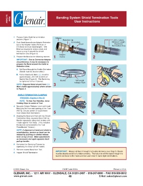
1. Prepare Cable Braid for termination Adapter
process (Figure 1). Retention Lip .400 (1.2mm)
2. Push Braid forward over Adapter Retention Conductors Minimum Length
Braid Over
Lip to the Adapter Incline Point (or .4" Braid Termination Area
[10.2mm] minimum braid length). Milk
Braid as required to remove slack and
insure a snug fit around the shield
termination area (Figure 2). Adapter
3. Prepare the Band in the following manner: 1 Incline 2
IMPORTANT: Due to Connector/Adapter
circumference, it may be necessary to
prepare the Band around the Cable or
Retention Area.
A. Roll Band through the Buckle Slot twice.
(Bands must be double-coiled.)
B. Pull on Band until Mark ( ) is within
approximately .250 inch (6.4mm) of
Buckle Slot (Figure 3). The Band may
Tail Length
be tightened further if desired. Buckle Indicator Mark
NOTE: Prepared Band should have ( ) 3 4
Mark visible approximately where shown
in Figure 3.
SHIELD TERMINATION CLAMPING
PROCESS: (Figures 4 thru 8):
NOTE: To free Tool Handles, move
Holding Clips to center of Tool.
4. Squeeze Gripper Release Lever and insert
Band into the front end opening of the Tool.
(NOTE: Circular portion of looped band
must always face downward.) 5 6
5. Aligning the Band and Tool with the Shield
Termination Area, squeeze Black Pull-Up
Handle repeatedly using short strokes until
it locks against Tool Body. (This indicates
the Band is compressed to the Tool
Precalibrated Tension.)
NOTE: If alignment of band and shield is
unsatisfactory, tension on band can be
relaxed by pushing on slotted release
lever on top of tool. Make adjustments
as necessary and again squeeze black 7 8
pull-up handle..
6. Complete the Clamping Process by
squeezing the Gray Cut-Off Handle.
7. Remove excess Band from Tool.
IMPORTANT: Always roll band through the buckle slot twice (see Step 3). Bands
8. Inspect Shield Termination.
must be double-coiled to function correctly. The failure to roll the band through the
buckle slot twice is the most common user error in band style terminations.
© 2005 Glenair, Inc. CAGE Code 06324 Printed in U.S.A.
GLENAIR, INC. • 1211 AIR WAY • GLENDALE, CA 91201-2497 • 818-247-6000 • FAX 818-500-9912
www.glenair.com 48 E-Mail: sales@glenair.com