
Page 55 - Circular Connector Backshells and Accessories
P. 55
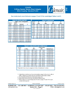
310-034
                          O-Ring Sealed Shrink Boot Adapter                                                          310
                               Direct Coupling - Standard Profile


                    See inside back cover fold-out or pages 13 and 14 for unabridged Tables I and II.


                      TABLE III: FRONT ADAPTER                           TABLE IV: DIMENSIONS
                           J Max - Conn. Designator      Shell     E           F            G            H
                Shell    A-E-F                           Size     Max         Max          Max          Max
                 Size    J-H-L-S   D-B-G-K      C        08/09  .639 (16.2)  .810 (20.6)  .750 (19.1)  .920 (23.4)
                08/09 1.180 (30.0) 1.250 (31.8)          10/11  .664 (16.9)  .840 (21.3)  .810 (20.6)  .980 (24.9)
                10/11 1.180 (30.0) 1.250 (31.8)          12/13  .688 (17.5)  .860 (21.8)  .870 (22.1) 1.040 (26.4)
                12/13 1.180 (30.0) 1.250 (31.8) 1.735 (44.1)  14/15  .705 (17.9)  .890 (22.6)  .920 (23.4) 1.110 (28.2)
                14/15 1.180 (30.0) 1.250 (31.8) 1.915 (48.6)  16/17  .732 (18.6)  .910 (23.1)  .980 (24.9) 1.170 (29.7)
                16/17 1.380 (35.0) 1.560 (39.6) 1.915 (48.6)  18/19  .748 (19.0)  .920 (23.4) 1.020 (25.9) 1.190 (30.2)
                18/19 1.380 (35.0) 1.560 (39.6) 1.915 (48.6)  20/21  .773 (19.6)  .940 (23.9) 1.080 (27.4) 1.250 (31.8)
                20/21 1.380 (35.0) 1.560 (39.6) 1.915 (48.6)  22/23  .800 (20.3)  .980 (24.9) 1.140 (29.0) 1.330 (33.8)
                22/23 1.380 (35.0) 1.560 (39.6) 1.915 (48.6)  24/25  .823 (20.9) 1.010 (25.7) 1.200 (30.5) 1.400 (35.6)
                24/25 1.380 (35.0) 1.560 (39.6) 1.915 (48.6)  28  1.041 (26.4) 1.180 (30.0) 1.480 (37.6) 1.640 (41.7)
                28/29 1.610 (40.9) 1.560 (39.6) 1.915 (48.6)  32  1.092 (27.7) 1.370 (34.8) 1.610 (40.9) 1.880 (47.8)
                32/33 1.610 (40.9) 1.750 (44.5) 1.915 (48.6)
                  36  1.610 (40.9) 1.750 (44.5) 1.915 (48.6)
                  40  1.610 (40.9) 2.190 (55.6) 1.915 (48.6)


                                           TABLE V: CABLE ENTRY AND SHRINK BOOT
                                 Shell                     L        Cable Entry
                                 Size       K Max         Max          Min       Shrink Boot *
                                  08      .500 (12.7)  .688 (17.5)  .250  (6.4)  770-001S103
                                 10/11    .500 (12.7)  .803 (20.4)  .355  (9.0)  770-001S103
                                 12/13    .500 (12.7)  .938 (23.8)  .491 (12.5)  770-001S104
                                 14/15    .500 (12.7)  1.063 (27.0)  .565 (14.4)  770-001S104
                                 16/17    .500 (12.7)  1.238 (31.4)  .690 (17.5)  770-001S106
                                  18      .500 (12.7)  1.310 (33.3)  .769 (19.5)  770-001S106
                                  20      .500 (12.7)  1.436   (36.5)  .844 (21.4)  770-001S107
                                  22      .500 (12.7)  1.560 (39.6)  1.019 (25.9)  770-001S107
                                  24      .500 (12.7)  1.686 (42.8)  1.134 (28.8)  770-001S108
                                  28      .687 (17.4)  2.062 (52.4)  1.369 (34.8)  770-001S108
                                  32      .687 (17.4)  2.312 (58.7)  1.615 (41.0)  770-001S109
                                  36      .687 (17.4)  2.562 (65.1)  1.830 (46.5)  Consult Factory
                                  40      .687 (17.4)  2.812 (71.4)  2.045 (51.9)  Consult Factory
                               *  Equivalent boot may be suppplied in lieu of stated part number.


                               1. Cable Entry is defined as the accomodation range for the wire bundle or
                                  cable.  Dimensions shown are not intended for inspection criteria.
                               2. See Shrink Boot Reference Information (page 40).
                               3. Metric dimensions (mm) are indicated in parentheses.
                               4. When using Connector Designator B refer to pages 18 and 19 for part
                                  number development.

               © 2005 Glenair, Inc.                      CAGE Code 06324                             Printed in U.S.A.
               GLENAIR, INC. • 1211 AIR WAY • GLENDALE, CA 91201-2497 • 818-247-6000 • FAX 818-500-9912
               www.glenair.com                       Series 310 -  Page 5               E-Mail: sales@glenair.com
                                                           REV. 13 JUNE 2010