
Page 52 - Circular Connector Backshells and Accessories
P. 52
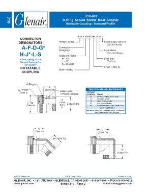
310-001
                                                    O-Ring Sealed Shrink Boot Adapter
                                                       Rotatable Coupling - Standard Profile
       310


                                                                 310 F S 001 M 16 D T
                  CONNECTOR
                DESIGNATORS                       Product Series                      Shrink Boot (Table III -
                                                                                         Omit for None)
                   A-F-D-G*                       Connector                           Drain Holes
                                                  Designator
                 H-J*-L-S                         Angle and Profile                      (Omit for None)


                * Conn. Desig. G & J -              H = 45°                           Shell Size
                 Consult Factory For                J = 90°                              (Table I)
                     45° and 90°                    S = Straight
                  ROTATABLE                       Basic Part No.                      Finish (Table II)
                   COUPLING


                       O-Ring
                                         F
                A Thread              (Table III)  Drain Holes            TABLE II - STANDARD FINISHES
                (Table I)                                                GLENAIR
                                                   4 Places Optional     SYMBOL  FINISH
                                                                           B     Cadmium Plate, Olive Drab
                                                                           C     Anodize, Black
                                                                           G     Hard Coat, Anodic
                       C Typ                      Cable  E (Table III)     M     Electroless Nickel
                      (Table I)                   Entry                    NF    Cadmium Plate, Olive Drab Over
                                                                                   Electroless Nickel
                                                                        See Back Cover for Complete Finish Information
                                                                               and Additional Finish Options


                                G                                                    J
                             (Table IV)                                          (Table IV)


                                             H (Table IV)


                                                                                                     K
                                                                                                 (Table IV)


             © 2005 Glenair, Inc.                      CAGE Code 06324                            Printed in U.S.A.
             GLENAIR, INC. • 1211 AIR WAY • GLENDALE, CA 91201-2497 • 818-247-6000 • FAX 818-500-9912
             www.glenair.com                       Series 310 - Page 2                E-Mail: sales@glenair.com