
Page 53 - Circular Connector Backshells and Accessories
P. 53
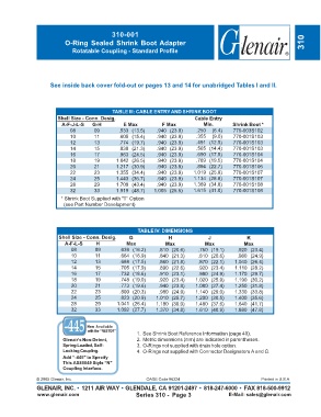
310-001
                          O-Ring Sealed Shrink Boot Adapter                                                          310
                             Rotatable Coupling - Standard Profile


                    See inside back cover fold-out or pages 13 and 14 for unabridged Tables I and II.


                                            TABLE III: CABLE ENTRY AND SHRINK BOOT
                       Shell Size - Conn. Desig.                           Cable Entry
                         A-F-J-L-S  G-H         E Max          F Max           Min.       Shrink Boot *
                            08       09       .533 (13.5)    .940 (23.9)    .250  (6.4)   770-003S102
                            10       11       .605 (15.4)    .940 (23.9)    .355  (9.0)   770-001S103
                            12       13       .774 (19.7)    .940 (23.9)    .491 (12.5)   770-001S103
                            14       15       .838 (21.3)    .940 (23.9)    .565 (14.4)   770-001S103
                            16       17       .963 (24.5)    .940 (23.9)    .690 (17.5)   770-001S104
                            18       19      1.042 (26.5)    .940 (23.9)    .769 (19.5)   770-001S104
                            20       21      1.217 (30.9)    .940 (23.9)    .894 (22.7)   770-001S106
                            22       23      1.355 (34.4)    .940 (23.9)   1.019 (25.9)   770-001S107
                            24       25      1.443 (36.7)    .940 (23.9)   1.134 (28.8)   770-001S107
                            28       29      1.709 (43.4)    .940 (23.9)   1.369 (34.8)   770-001S108
                            32       33      1.919 (48.7)   1.005 (25.5)   1.615 (41.0)   770-001S108

                        * Shrink Boot Supplied with "T" Option


                          (see Part Number Development)

                                                      TABLE IV: DIMENSIONS
                       Shell Size - Conn. Desig.  G              H               J             K
                          A-F-L-S     H          Max            Max            Max            Max
                            08       09        .639 (16.2)    .810 (20.6)    .750 (19.1)    .920 (23.4)
                            10       11        .664 (16.9)    .840 (21.3)    .810 (20.6)    .980 (24.9)
                            12       13        .688 (17.5)    .860 (21.8)    .870 (22.1)   1.040 (26.4)
                            14       15        .705 (17.9)    .890 (22.6)    .920 (23.4)   1.110 (28.2)
                            16       17        .732 (18.6)    .910 (23.1)    .980 (24.9)   1.170 (29.7)
                            18       19        .748 (19.0)    .920 (23.4)   1.020 (25.9)   1.190 (30.2)
                            20       21        .773 (19.6)    .940 (23.9)   1.080 (27.4)   1.250 (31.8)
                            22       23        .800 (20.3)    .980 (24.9)   1.140 (29.0)   1.330 (33.8)
                            24       25        .823 (20.9)   1.010 (25.7)   1.200 (30.5)   1.400 (35.6)
                            28       29       1.041 (26.4)   1.180 (30.0)   1.480 (37.6)   1.640 (41.7)
                            32       33       1.092 (27.7)   1.370 (34.8)   1.610 (40.9)   1.880 (47.8)


                                  Now Available
                                   with the “NESTOR”
                                                     1. See Shrink Boot Reference Information (page 40).
                         Glenair’s Non-Detent,       2. Metric dimensions (mm) are indicated in parentheses.
                         Spring-Loaded, Self-        3. O-Rings not supplied with drain hole option.
                         Locking Coupling.           4. O-Rings not supplied with Connector Designators A and G.
                         Add “-445” to Specify
                         This AS85049 Style “N”
                         Coupling Interface.
               © 2005 Glenair, Inc.                      CAGE Code 06324                             Printed in U.S.A.
               GLENAIR, INC. • 1211 AIR WAY • GLENDALE, CA 91201-2497 • 818-247-6000 • FAX 818-500-9912
               www.glenair.com                       Series 310 -  Page 3               E-Mail: sales@glenair.com