
Page 56 - Circular Connector Backshells and Accessories
P. 56
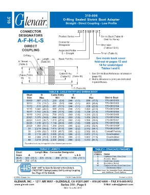
310-006
                                                     O-Ring Sealed Shrink Boot Adapter
                                                       Straight  -  Direct Coupling - Low Profile
       310

                  CONNECTOR                                     310 F S 006 M 16 T
                DESIGNATORS                      Product Series                     Shrink Boot (Table III -
               A-F-H-L-S                         Connector                            Omit for None)

                     DIRECT                      Designator                         Shell size
                                                                                      (Tables I & III)
                   COUPLING                      Angle and Profile
                                                   S = Straight                     Finish (Table II)
                    O-Ring
                                   Length        Basic Part No.                 See inside back cover
                A Thread          (Table IV)                                  fold-out or pages 13 and
                (Table I)                                                         14 for unabridged
                                                                                    Tables I and II.
                   D    C                         Cable Entry   F         1. See Shrink Boot Reference Information
                 (Table  (Table                   (Table III) (Table III)   (page 40).
                  III)  I)                                                2. Metric dimensions (mm) are indicated
                                                                            in parentheses.

                                                             E (Table III)
                                         TABLE III: CABLE ENTRY AND SHRINK BOOT
                       Shell      D        Cable Entry      E              F
                       Size      Max          Min          Min            Max          Shrink Boot
                       08/09   .657 (16.7)  .250  (6.4)  .044  (1.1)   .688 (17.5)     770-001S103
                       10/11   .774 (19.7)  .355  (9.0)  .044  (1.1)   .803 (20.4)     770-001S103
                       12/13   .818 (20.8)  .491 (12.5)  .044  (1.1)   .938 (23.8)     770-001S104
                       14/15  1.024 (26.0)  .565 (14.4)  .044  (1.1)  1.063 (27.0)     770-001S104
                       16/17  1.152 (29.3)  .690 (17.5)  .069  (1.8)  1.238 (31.4)     770-001S106
                       18/19  1.243 (31.6)  .769 (19.5)  .069  (1.8)  1.310 (33.3)     770-001S106
                       20/21  1.370 (34.8)  .844 (21.4)  .069  (1.8)  1.436 (36.5)     770-001S106
                       22/23  1.443 (36.7)  1.019 (25.9)  .069  (1.8)  1.560 (39.6)    770-001S107
                       24/25  1.618 (41.1)  1.134 (28.8)  .069  (1.8)  1.686 (42.8)    770-001S108
                       28/29  1.969 (50.0)  1.369 (34.8)  .086  (2.2)  2.062 (52.4)    770-001S108*
                        32    2.219 (56.4)  1.615 (41.0)  .086  (2.2)  2.312 (58.7)    770-001S109*
                        36    2.469 (62.7)  1.830 (46.5)  .086  (2.2)  2.562 (65.1)    Consult Factory
                        40    2.719 (69.1)  2.045 (51.9)  .086  (2.2)  2.812 (71.4)     Overmolded
                        44    2.969 (75.4)  2.300 (58.4)  .086  (2.2)  3.062 (77.8)     Overmolded
                        48    3.219 (81.8)  2.550 (64.8)  .086  (2.2)  3.312 (84.1)     Overmolded
                     *Equivalent boot may be supplied in lieu of stated part number.

                                 TABLE IV: LENGTH                              TABLE II - STANDARD FINISHES
              Shell           Length Max - Connector Designator               GLENAIR
              Sizes     A            F            H           L & S           SYMBOL  FINISH
              08-25  .540 (13.7)  .625 (15.9)  .688 (17.5)  .750 (19.1)         B     Cadmium Plate, Olive Drab
                                                                                C
                                                                                      Anodize, Black
              28-48  .702 (17.8)     ---         ---           ---              G     Hard Coat, Anodic
                                                                                M     Electroless Nickel
                                                                                NF    Cadmium Plate, Olive Drab Over
                           Add “-445” to Specify Glenair’s Non-Detent,                  Electroless Nickel
                           ("NESTOR") Spring-Loaded, Self-Locking Coupling.  See Back Cover for Complete Finish Information
                           See Page 41 for Details.                                 and Additional Finish Options
             © 2005 Glenair, Inc.                      CAGE Code 06324                            Printed in U.S.A.
             GLENAIR, INC. • 1211 AIR WAY • GLENDALE, CA 91201-2497 • 818-247-6000 • FAX 818-500-9912
             www.glenair.com                       Series 310 - Page 6                E-Mail: sales@glenair.com
                                                     REV. 13 JUNE 2010