
Page 83 - Circular Connector Backshells and Accessories
P. 83
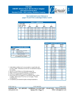
319-044
                      EMI/RFI Shield Sock Shrink Boot Adapter                                                        319
                                   with Optional Shrink Boot
                     Standard Profile - Self Locking - Rotatable Coupling


                                              See inside back cover fold-out or
                                      pages 13 and 14 for unabridged Tables I and II.


                                                    TABLE III: DIMENSIONS
                                  Shell Size
                                Conn. Desig.      F           G           H            J
                                 A-F-L-S  H      Max         Max         Max         Max
                                   08    09    .986 (25.0) 1.045 (26.5)  1.096 (27.8) 1.155 (29.3)
                                   10     11  1.016 (25.8) 1.075 (27.3)  1.166 (29.6) 1.225 (31.1)
                                   12    13   1.038 (26.4) 1.097 (27.9)  1.226 (31.1) 1.285 (32.6)
                                   14    15   1.056 (26.8) 1.125 (28.6)  1.286 (32.7) 1.345 (34.2)
                                   16    17   1.066 (27.1) 1.145 (29.1)  1.346 (34.2) 1.405 (35.7)
                                   18    19   1.106 (28.1) 1.165 (29.6)  1.396 (35.5) 1.455 (37.0)
                                   20    21   1.136 (28.9) 1.195 (30.4)  1.466 (37.2) 1.525 (38.7)
                                   22    23   1.156 (29.4) 1.215 (30.9)  1.516 (38.5) 1.575 (40.0)
                                   24    25   1.186 (30.1) 1.245 (31.6)  1.586 (40.3) 1.645 (41.8)


                                                                            TABLE IV: CABLE ENTRY/SHRINK BOOT
                                                                             Dash      Cable          Shrink
                                                                              No.      Entry          Boot
                      TABLE II: STANDARD FINISHES                              01    .188  (4.8)       n/a
                    GLENAIR                                                    02    .250  (6.4)       n/a
                    SYMBOL  FINISH                                             03    .312  (7.9)   770-001S103
                       B    Cadmium Plate, Olive Drab
                       M    Electroless Nickel                                 04    .375  (9.5)   770-001S103
                      NF    Cadmium Plate, Olive Drab Over                     05    .438 (11.1)   770-001S103
                               Electroless Nickel                              06    .500 (12.7)   770-001S104
                    See Back Cover for Complete Finish Information             07    .562 (14.3)   770-001S104
                           and Additional Finish Options
                                                                               08    .625 (15.9)   770-001S104
                                                                               09    .688 (17.5)   770-001S105
                                                                               10    .750 (19.1)   770-001S105
                                                                               11    .812 (20.6)   770-001S105
                                                                               12    .875 (22.2)   770-001S106
                                                                               13    .938 (23.8)   770-001S106
                                                                               14   1.000 (25.4)   770-001S106
               1. Cable Entry is defined as the accomodation range for the wire  15  1.250 (31.8)  770-001S107
                 bundle or cable.  Dimensions shown are not intended for inspec-  16  1.500 (38.1)  770-001S107
                 tion criteria.                                                17   1.750 (44.5)       n/a
               2. See Shrink Boot Reference Information (page 40).             18   2.000 (50.8)       n/a
               3. Metric dimensions (mm) are indicated in parentheses.         19   1.125 (28.6)       n/a
               4. O-Ring not supplied with Connector Designator A.             20   1.375 (34.9)       n/a
               5. When maximum entry (page 21) is exceeded, Style 2 will be    21   1.625 (41.3)       n/a
                 supplied.  Dimensions  F, G, H & J will not apply.  Please    22   1.062 (27.0)       n/a
                 consult factory.                                              23   1.188 (30.2)       n/a
               6. Consult factory for shorter lengths on straight backshells.  24   1.875 (47.6)       n/a


               © 2005 Glenair, Inc.                      CAGE Code 06324                             Printed in U.S.A.
               GLENAIR, INC. • 1211 AIR WAY • GLENDALE, CA 91201-2497 • 818-247-6000 • FAX 818-500-9912
               www.glenair.com                       Series 319 - Page 11               E-Mail: sales@glenair.com