
Page 157 - Circular Connector Backshells and Accessories
P. 157
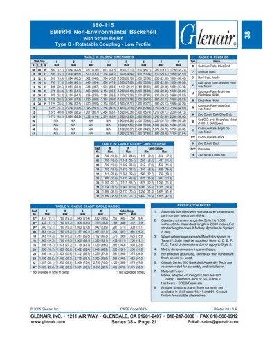
380-115
                        EMI/RFI  Non-Environmental  Backshell
                                        with Strain Relief                                                           38
                           Type B - Rotatable Coupling - Low Profile


                                        TABLE III: ELBOW DIMENSIONS                          TABLE II: FINISHES
                 Shell Size  C     D       E       F       R        S       T       U     Sym       Finish
                A F,L,S H  Max    Max     Max      Max     Max     Max     Max     Max     B  Cadmium Plate, Olive Drab
                08 08 09  .500  (12.7) 1.684  (42.8)  457  (11.6) 1.674  (42.5)  .910 (23.11) 1.910 (48.77) .780 (19.81) 1.780 (45.21)  C*  Anodize, Black
                10 10 11  .595  (15.1) 1.804  (45.8)  .520  (13.2) 1.734  (44.0) .970 (24.64) 1.970 (50.04) .810 (20.57) 1.810 (45.97)
                12 12 13  .610  (15.5) 1.824  (46.3)  .582  (14.8) 1.794  (45.6) 1.030 (26.16) 2.030 (50.56) .830 (21.08) 1.830 (46.48)  G*  Hard Coat, Anodic
                14 14 15  .700  (17.8) 1.894  (48.1)  .645  (16.4) 1.884  (47.9) 1.090 (27.68) 2.090 (53.09) .850 (21.59) 1.850 (46.99)  J  Gold Iridite over Cadmium Plate
                16 16 17  .885  (22.5) 1.984  (50.4)  .738  (18.7) 1.994  (50.6) 1.150 (29.21 2.150 (54.61) .880 (22.35) 1.880 (47.75)  over Nickel
                18 18 19  .975  (24.8) 2.154  (54.7)  .926  (23.5) 2.184  (55.5) 1.200 (30.48) 2.200 (55.88) .900 (22.86) 1.900 (48.26)  LF  Cadmium Plate, Bright over
                20 20 21  .975  (24.8) 2.154  (54.7)  .926  (23.5) 2.184  (55.5) 1.270 (32.26) 2.270 (57.66) .930 (23.62) 1.930 (49.02)  Electroless Nickel
                22 22 23 1.125  (28.6) 2.264  (57.5) 1.020  (25.9) 2.334  (59.3) 1.330 (33.78) 2.330 (59.18) .950 (24.13) 1.950 (49.53)  M  Electroless Nickel
                24 24 25 1.125  (28.6) 2.264  (57.5) 1.020  (25.9) 2.334  (59.3) 1.390 (35.31) 2.390 (60.71) .980 (24.13) 1.980 (50.29)  Cadmium Plate, Olive Drab
                28      1.225  (31.1) 2.434  (61.8) 1.145  (29.1) 2.384  (60.6) 1.460 (37.08) 2.460 (62.48) 1.150 (29.21) 2.150 (54.61)  N  over Nickel
                32      1.575  (40.0) 2.684  (68.2) 1.207  (30.7) 2.484  (63.1) 1.590 (40.38) 2.590 (65.79) 1.210 (30.73) 2.210 (56.13)  NC  Zinc Cobalt, Dark Olive Drab
                36      1.775  (45.1) 2.684  (68.2) 1.238  (31.4) 2.574  (65.4) 1.690 (42.93) 2.690 (68.33) 1.240 (31.50) 2.240 (56.90)
                40        N/A     N/A     N/A     N/A   1.900 (48.26) 2.200 (55.88) 1.250 (31.75) 1.590 (40.38)  NF  Cad/O.D. over Electroless Nickel
                44        N/A     N/A     N/A     N/A   2.030 (51.56) 2.360 (59.94) 1.300 (33.02) 1.640 (41.65)  (1000 Hr. Salt Spray)
                48        N/A     N/A     N/A     N/A   2.180 (53.37) 2.530 (64.26) 1.370 (34.79) 1.720 (43.68)  T  Cadmium Plate, Bright Dip
                61        N/A     N/A     N/A     N/A   1.290 (32.76) 1.490 (37.85) .880 (22.35) 1.100 (27.94)  over Nickel
                                                                                          U** Cadmium Plate, Black
                                                TABLE IV: CABLE CLAMP CABLE RANGE         UC  Zinc Cobalt, Black
                                             Dash   N       P         Cable Range         Z1** Passivate
                                              No.  Max      Max     Min                          Max
                                              04  .780  (19.8)  .957  (24.3)  .125    (3.2)  .312    (7.9)  ZN  Zinc Nickel, Olive Drab
                                              06  .780  (19.8) 1.145  (29.1)  .250    (6.4)  .437  (11.1)
                                              08  .780  (19.8) 1.332  (33.8)  .312    (7.9)  .562  (14.3)
                                              10  .780  (19.8) 1.332  (33.8)  .350    (8.9)  .625  (15.9)
                                              12  .811  (20.6) 1.551  (39.4)  .500  (12.7)  .750  (19.1)
                                              16  .905  (23.0) 1.770  (45.0)  .625  (15.9)  .937  (23.8)
                                              20  1.092  (27.7)  2.113  (53.7)  .875  (22.2) 1.250  (31.8)
                                              24  1.124  (28.5) 2.363  (60.0) 1.000  (25.4) 1.375  (34.9)
                                              28  1.399  (35.5) 2.770  (70.4) 1.250  (31.8) 1.625  (41.3)
                                              32  1.399  (35.5) 3.020  (76.7) 1.437  (36.5) 1.875  (47.6)


                           TABLE V: CABLE CLAMP CABLE RANGE                        APPLICATION NOTES
                Dash  J        K       L        M        Cable Range     1.
                No.   Max     Max     Max      Max      Min**          Max  part number, space permitting.
                03*  .437  (11.1)  .760  (19.3)  .843  (21.4)  .630  (16.0)  .156    (4.0)  .250    (6.4)  2.   Standard minimum length for Style I is 1.500
                04*  .437  (11.1)  .760  (19.3)  .906  (23.0)  .755  (19.2)  .188    (4.8)  .312    (7.9)  inches, Style II standard length is 2.000 inches.For
                06*  .500  (12.7)  .760  (19.3) 1.093  (27.8)  .942  (23.9)  .281    (7.1)  .438  (11.1)  shorter lengths consult factory. Appklies to Symbol
                08  .563  (14.3)  .760  (19.3) 1.187  (30.1) 1.067  (27.1)  .344    (8.7)  .562  (14.3)  S only.
                10  .563  (14.3)  .760  (19.3) 1.281  (32.5) 1.192  (30.3)  .375    (9.5)  .625  (15.9)  3.   When cable range exceeds Max Entry shown in
                12  .563  (14.3)  .760  (19.3) 1.500  (38.1) 1.380  (35.1)  .438  (11.1)  .750  (19.1)  Table IV, Style II will be supplied. Note: C, D, E, F,
                16  .656  (16.7) 1.073  (27.3) 1.719  (43.7) 1.535  (39.0)  .562  (14.3)  .938  (23.8)  R, S, T and U dimensions do not apply to Style II.
                20  .656  (16.7) 1.323  (33.6) 2.062  (52.4) 1.848  (46.9)  .750  (19.1) 1.250  (31.8)  4.   Metric dimensions are in parentheses.
                24  .656  (16.7) 1.323  (33.6) 2.312  (58.7) 2.255  (57.3)  .781  (19.8) 1.375  (34.9)  5.   For effective grounding, connector with conductive
                28  1.188  (30.2) 1.572  (39.9) 2.719  (69.1) 2.505  (63.6)  .969  (24.6) 1.625  (41.3)
                32* 1.187  (30.1) 1.572  (39.9) 2.969  (75.4)  2.755 (70.0) 1.125  (28.6) 1.875  (47.6)  6.   Glenair Series 600 Backshell Assembly Tools are
                40* 1.125  (28.6) 1.572  (39.9) 3.531  (89.7)  3.255 (82.7) 1.469  (37.3) 2.375  (60.3)  recommended for assembly and installation.
               *  Not available in Style M clamp.                                                                 ** Not Applicable Style D  7.   Material/Finish:
                                                                                 Elbow, adapter, coupling nut, ferrules and
                                                                                      clamp - Aluminim alloy or SST/Table II.
                                                                                 Hardware - CRES/Passivate
                                                                         8.   Angular functions A and B are currently not
                                                                            available in shell sizes 40, 44 and 61. Consult
                                                                            factory for suitable alternatives.


               © 2005 Glenair, Inc.                      CAGE Code 06324                             Printed in U.S.A.
               GLENAIR, INC. • 1211 AIR WAY • GLENDALE, CA 91201-2497 • 818-247-6000 • FAX 818-500-9912
               www.glenair.com                       Series 38 -  Page 21               E-Mail: sales@glenair.com