
Page 161 - Circular Connector Backshells and Accessories
P. 161
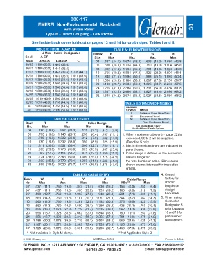
380-117
                        EMI/RFI  Non-Environmental  Backshell
                                        with Strain Relief                                                           38
                             Type B - Direct Coupling - Low Profile

                    See inside back cover fold-out or pages 13 and 14 for unabridged Tables I and II.

                      TABLE III: FRONT ADAPTER                        TABLE IV: ELBOW DIMENSIONS
                           J Max - Conn. Designator      Elbow     E            F           G            H
                Shell    A-E-F                            Size    Max          Max         Max          Max
                 Size    J-H-L-S   D-B-G-K      C          04   .567 (14.4)  1.674 (42.5)  .636 (16.2) 1.684 (42.8)
                08/09 1.180 (30.0) 1.440 (36.6)            06   .630 (16.0)  1.734 (44.0)  .710 (18.0) 1.804 (45.8)
                10/11 1.180 (30.0) 1.440 (36.6)            08   .692 (17.6)  1.794 (45.6)  .731 (18.6) 1.824 (46.3)
                12/13 1.180 (30.0) 1.440 (36.6)  1.735 (44.1)  10  .755 (19.2)  1.884 (47.9)  .825 (21.0) 1.894 (48.1)
                14/15 1.180 (30.0) 1.440 (36.6)  1.915 (48.6)  12  .848 (21.5)  1.994 (50.6)  .988 (25.1) 1.984 (50.4)
                16/17 1.380 (35.0) 1.560 (39.6) 1.915 (48.6)  16  1.036 (26.3)  2.184 (55.5)  1.087 (27.6) 2.154 (54.7)
                18/19 1.380 (35.0) 1.560 (39.6) 1.915 (48.6)  20  1.130 (28.7)  2.334 (59.3)  1.325 (33.7) 2.264 (57.5)
                20/21 1.380 (35.0) 1.560 (39.6) 1.915 (48.6)  24  1.255 (31.9)  2.384 (60.6)  1.337 (34.0) 2.434 (61.8)
                22/23 1.380 (35.0) 1.560 (39.6) 1.915 (48.6)  28  1.317 (33.5)  2.484 (63.1)  1.827 (46.4) 2.684 (68.2)
                24/25 1.380 (35.0) 1.560 (39.6) 1.915 (48.6)  32  1.348 (34.2)  2.574 (65.4)  2.027 (51.5) 2.684 (68.2)
                28/29 1.610 (40.9) 1.560 (39.6) 1.915 (48.6)
                32/33 1.610 (40.9) 1.750 (44.5) 1.915 (48.6)                 TABLE Il: STANDARD FINISHES
                  36  1.610 (40.9) 1.750 (44.5) 1.915 (48.6)                 GLENAIR
                  40  1.610 (40.9) 2.190 (55.6) 1.915 (48.6)                 SYMBOL  FINISH
                                                                                B    Cadmium Plate, Olive Drab
                                                                                M    Electroless Nickel
                                  TABLE X: CABLE ENTRY                         NF    Cadmium Plate, Olive Drab
                 Dash       T            V            Cable Range                        Over Electroless Nickel
                 No.       Max          Max          Min         Max               See Inside Back Cover
                  04    .780 (19.8)  .957 (24.3)  .125  (3.2)  .312  (7.9)       for Additional Finish Options
                  06    .780 (19.8)  1.145 (29.1)  .250  (6.4)  .437 (11.1)  1. When maximum cable entry (page 22) is
                  08    .780 (19.8)  1.332 (33.8)  .312  (7.9)  .562 (14.3)  exceeded, Style 2 will be supplied.
                  10    .780 (19.8)  1.332 (33.8)  .350  (8.9)  .625 (15.9)  (Function S only.)
                  12    .811 (20.6)  1.551 (39.4)  .500 (12.7)  .750 (19.1)  2. Metric dimensions (mm) are indicated in
                  16    .905 (23.0)  1.770 (45.0)  .625 (15.9)  .937 (23.8)  parentheses.
                  20   1.092 (27.7)  2.113 (53.7)  .875 (22.2) 1.250 (31.8)  3. Cable range is defined as the accommo-
                  24   1.124 (28.5)  2.363 (60.0)  1.000 (25.4) 1.375 (34.9)  dations range for
                  28   1.399 (35.5)  2.770 (70.4)  1.250 (31.8) 1.625 (41.3)  the wire bundle or cable.  Dimensions
                  32   1.399 (35.5)  3.020 (76.7)  1.437 (36.5) 1.875 (47.6)  shown are not intended for inspection
                                                                             criteria.
                                             TABLE XI: CABLE ENTRY                                4. Consult
                Dash      W           X            Y            Z             Cable Range           factory for
                No.      Max         Max          Max          Max        Min **        Max         shorter
                03*   .437 (11.1)  .760 (19.3)  .843 (21.4)  .630 (16.0)  .156  (4.0)  .250  (6.4)  lengths on
                04*   .437 (11.1)  .760 (19.3)  .906 (23.0)  .755 (19.2)  .188  (4.8)  .312  (7.9)  straight
                06*   .500 (12.7)  .760 (19.3) 1.093 (27.8)  .942 (23.9)  .281  (7.1)  .438 (11.1)  backshells.
                 08   .563 (14.3)  .760 (19.3) 1.187 (30.1)  1.067 (27.1)  .344  (8.7)  .562 (14.3)  5. When using
                 10   .563 (14.3)  .760 (19.3) 1.281 (32.5)  1.192 (30.3)  .375  (9.5)  .625 (15.9)  Connector
                 12   .563 (14.3)  .760 (19.3) 1.500 (38.1)  1.380 (35.1)  .438 (11.1)  .750 (19.1)  Designator B
                 16   .656 (16.7)  1.073 (27.3) 1.719 (43.7)  1.535 (39.0)  .562 (14.3)  .938 (23.8)  refer to pages
                 20   .656 (16.7)  1.323 (33.6) 2.062 (52.4)  1.848 (46.9)  .750 (19.1)  1.250 (31.8)  18 and 19 for
                 24   .656 (16.7)  1.323 (33.6) 2.312 (58.7)  2.255 (57.3)  .781 (19.8)  1.375 (34.9)  part number
                 28  1.188 (30.2)  1.572 (39.9) 2.719 (69.1)  2.505 (63.6)  .969 (24.6)  1.625 (41.3)  development.
                32* 1.187 (30.1)  1.572 (39.9) 2.969 (75.4)  2.755 (70.0) 1.125 (28.6)  1.875 (47.6)
                40* 1.125 (28.6)  1.572 (39.9) 3.531 (89.7)  3.255 (82.7) 1.469 (37.3)  2.375 (60.3)
                 *  Not available in Style M clamp.                                                    ** Not Applicable Style D
               © 2005 Glenair, Inc.                      CAGE Code 06324                             Printed in U.S.A.
               GLENAIR, INC. • 1211 AIR WAY • GLENDALE, CA 91201-2497 • 818-247-6000 • FAX 818-500-9912
               www.glenair.com                       Series 38 -  Page 25               E-Mail: sales@glenair.com