
Page 63 - Circular Connector Backshells and Accessories
P. 63
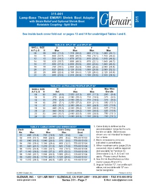
311-001
                 Lamp-Base  Thread  EMI/RFI  Shrink  Boot  Adapter
                          with Strain Relief and Optional Shrink Boot                                                311
                                Rotatable Coupling - Split Shell


                    See inside back cover fold-out  or pages 13 and 14 for unabridged Tables I and II.


                                               TABLE III: SPLIT 90° and SPLIT 45°
                           SHELL SIZE           D              E              F            G
                           A-F-L-S    H        Max            Max           Max           Max
                              08     09     .440 (11.2)   1.740 (44.2)   .680 (17.3)  1.680 (42.7)
                              10     11     .500 (12.7)   1.800 (45.7)   .750 (19.1)  1.740 (44.2)
                              12     13     .560 (14.2)   1.870 (47.5)   .810 (20.6)  1.810 (46.0)
                              14     15     .620 (15.7)   1.900 (48.3)   .870 (22.1)  1.840 (46.7)
                              16     17     .680 (17.3)   2.000 (50.8)   .930 (23.6)  1.940 (49.3)
                              18     19     .750 (19.1)   2.060 (52.3)  1.000 (25.4)  2.000 (50.8)
                              20     21     .820 (20.8)   2.120 (53.8)  1.060 (26.9)  2.060 (52.3)
                              22     23     .880 (22.4)   2.180 (55.4)  1.120 (28.4)  2.120 (53.8)
                              24     25     .940 (23.9)   2.240 (56.9)  1.180 (30.0)  2.340 (59.4)


                                           TABLE IV: ULTRA LOW-PROFILE SPLIT 90°
                            SHELL SIZE           H              J             K          Max Wire
                            A-F-L-S  H          Ref.          Max           Max           Bundle
                              08     09      .340  (8.6)  2.020 (51.3)    .681 (17.3)   .250  (6.4)
                              10     11      .270  (6.9)  2.180 (55.4)    .731 (18.6)   .375  (9.5)
                              12     13      .270  (6.9)  2.180 (55.4)    .731 (18.6)   .375  (9.5)
                              14     15      .280  (7.1)  2.250 (57.2)    .831 (21.1)   .500 (12.7)
                              16     17      .420 (10.7)  2.300 (58.4)    .981 (24.9)   .625 (15.9)
                              18     19      .640 (16.3)  2.330 (59.2)   1.181 (30.0)   .625 (15.9)
                              20     21      .640 (16.3)  2.330 (59.2)   1.181 (30.0)   .625 (15.9)
                              22     23      .540 (13.7)  2.480 (63.0)   1.181 (30.0)   .750 (19.1)
                              24     25      .540 (13.7)  2.480 (63.0)   1.181 (30.0)   .750 (19.1)


                          TABLE V: CABLE ENTRY AND SHRINK BOOT                  1. Cable Entry is defined as the
                Dash       L             M       Cable Entry      Shrink          accommodation  range for the wire
                 No.      Max           Max          Max          Boot            bundle or cable.  Dimensions
                  01    .448 (11.4)  .781 (19.8)  .125  (3.2)       n/a           shown are not intended for inspec-
                  02    .515 (13.1)  .968 (24.6)  .250  (6.4)  770-001S103        tion criteria.
                  03    .640 (16.3)  1.046 (26.6)  .375  (9.5)  770-001S103     2. Metric dimensions (mm) are
                  04    .765 (19.4)  1.156 (29.4)  .500 (12.7)  770-001S104       indicated in parentheses.
                  05    .920 (23.4)  1.219 (31.0)  .625 (15.9)  770-001S104     3. When maximum entry (page 21) is
                  06  1.015 (25.8)  1.343 (34.1)  .750 (19.1)  770-001S105        exceeded, Style 2 will be supplied
                  07  1.140 (29.0)  1.469 (37.3)  .875 (22.2)  770-001S106        (not available for Function C).
                  08  1.265 (32.1)  1.594 (40.5)  1.000 (25.4)  770-001S106       Dimensions D, E, F, & G will not
                  09  1.432 (36.4)  1.719 (43.7)  1.125 (28.6)  770-001S107       apply.  Please consult factory.
                  10  1.515 (38.5)  1.844 (46.8)  1.250 (31.8)  770-001S107     4. See Shrink Boot Reference Infor-
                                                                                  mation (pages 40 and 41).
                                                                                5. Angular function "C", low-profile split
                                                                                  elbow, not available with "S" con-
                                                                                  nector designator.
               © 2005 Glenair, Inc.                      CAGE Code 06324                             Printed in U.S.A.
               GLENAIR, INC. • 1211 AIR WAY • GLENDALE, CA 91201-2497 • 818-247-6000 • FAX 818-500-9912
               www.glenair.com                       Series 311 - Page 7                E-Mail: sales@glenair.com