
Page 118 - Circular Connector Backshells and Accessories
P. 118
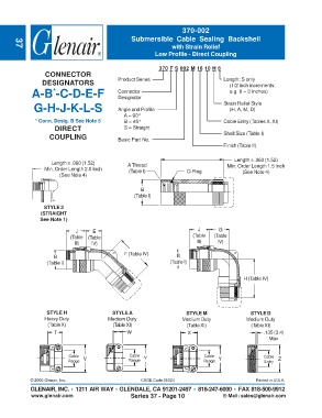
370-002
                                                   Submersible Cable Sealing Backshell
                                                                  with Strain Relief
       37
                                                            Low Profile - Direct Coupling


                                                              370 F S 002 M 16 10 H 6
                  CONNECTOR
                 DESIGNATORS                  Product Series                          Length: S only
                                                                                        (1/2 inch increments:
             A-B -C-D-E-F                     Connector                                 e.g. 6 = 3 inches)
                     *
                                              Designator
              G-H-J-K-L-S                     Angle and Profile                       Strain Relief Style
                                                                                        (H, A, M, D)
                                                A = 90°
              * Conn. Desig. B See Note 5       B = 45°                               Cable Entry (Tables X, XI)
                      DIRECT                    S = Straight
                    COUPLING                  Basic Part No.                          Shell Size (Table I)
                                                                                      Finish (Table II)

                                                                                          Length ± .060 (1.52)
                     Length ± .060 (1.52)         A Thread
                  Min. Order Length 2.0 Inch      (Table I)             O-Ring         Min. Order Length 1.5 Inch
                                                                                             (See Note 4)
                        (See Note 4)

                                                       B
                                                    (Table I)
                  STYLE 2
                 (STRAIGHT
                See Note 1)

                              J     E                                       J       G
                            (Table  (Table                                (Table  (Table
                             III)   IV)                                     III)    IV)

                                                F (Table IV)
                     B                                              B
                   (Table I)                                      (Table I)

                                                                                              H (Table IV)


                   STYLE H                  STYLE A                     STYLE M                 STYLE D
                  Heavy Duty              Medium Duty                 Medium Duty              Medium Duty
                   (Table X)                (Table XI)                  (Table XI)              (Table XI)
                      T                          W                      X                            .135 (3.4)
                                                                                                       Max


                           Cable  V               Cable  Y                     Cable  Y              Cable
                           Range                  Range                       Range                  Entry  Z


             © 2005 Glenair, Inc.                      CAGE Code 06324                            Printed in U.S.A.
             GLENAIR, INC. • 1211 AIR WAY • GLENDALE, CA 91201-2497 • 818-247-6000 • FAX 818-500-9912
             www.glenair.com                       Series 37 - Page 10                E-Mail: sales@glenair.com