
Page 121 - Circular Connector Backshells and Accessories
P. 121
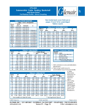
370-002
                        Submersible  Cable  Sealing  Backshell
                                        with Strain Relief                                                           37
                              Full Radius Profile - Direct Coupling


                                                                  See inside back cover fold-out or
                      TABLE III: FRONT ADAPTER
                           J Max - Conn. Designator                pages 13 and 14 for unabridged
                Shell    A-E-F                                               Tables I and II.
                 Size    J-H-L-S   D-B-G-K      C
                08/09 1.180 (30.0) 1.440 (36.6)                       TABLE IV: ELBOW DIMENSIONS
                10/11 1.180 (30.0) 1.440 (36.6)           Elbow     E           F           G            H
                12/13 1.180 (30.0) 1.440 (36.6)  1.735 (44.1)  Size  Max       Max         Max         Max
                14/15 1.180 (30.0) 1.440 (36.6)  1.915 (48.6)  03  .817 (20.8)  1.127 (28.6)  1.125 (28.6) 1.445 (36.7)
                16/17 1.380 (35.0) 1.560 (39.6) 1.915 (48.6)  04  .861 (21.9)  1.181 (30.0)  1.250 (31.8) 1.570 (39.9)
                18/19 1.380 (35.0) 1.560 (39.6) 1.915 (48.6)  06  .911 (23.1)  1.231 (31.3)  1.375 (34.9) 1.695 (43.1)
                20/21 1.380 (35.0) 1.560 (39.6) 1.915 (48.6)  08  .965 (24.5)  1.285 (32.6)  1.500 (38.1) 1.820 (46.2)
                22/23 1.380 (35.0) 1.560 (39.6) 1.915 (48.6)  10  1.014 (25.8)  1.334 (33.9)  1.625 (41.3) 1.945 (49.4)
                24/25 1.380 (35.0) 1.560 (39.6) 1.915 (48.6)  12  1.064 (27.0)  1.384 (35.2)  1.750 (44.5) 2.070 (52.6)
                28/29 1.610 (40.9) 1.560 (39.6) 1.915 (48.6)  16  1.172 (29.8)  1.492 (37.9)  2.000 (50.8) 2.320 (58.9)
                32/33 1.610 (40.9) 1.750 (44.5) 1.915 (48.6)  20  1.325 (33.7)  1.645 (41.8)  2.375 (60.3) 2.695 (68.5)
                  36  1.610 (40.9) 1.750 (44.5) 1.915 (48.6)  24  1.325 (33.7)  1.645 (41.8)  2.375 (60.3) 2.695 (68.5)
                  40  1.610 (40.9) 2.190 (55.6) 1.915 (48.6)  28  1.428 (36.3)  1.748 (44.4)  2.625 (66.7) 2.945 (74.8)

                                  TABLE X: CABLE ENTRY                        TABLE II: STANDARD FINISHES
                 Dash       T            V            Cable Range             GLENAIR
                 No.      Max          Max           Min         Max          SYMBOL FINISH
                  04    .780 (19.8)  .957 (24.3)  .125  (3.2)  .312  (7.9)       B    Cadmium Plate, Olive Drab
                                                                                 C
                                                                                      Anodize, Black
                  06    .780 (19.8)  1.145 (29.1)  .250  (6.4)  .437 (11.1)      G    Hard Coat, Anodic
                  08    .780 (19.8)  1.332 (33.8)  .387  (9.8)  .562 (14.3)      M    Electroless Nickel
                  10    .780 (19.8)  1.332 (33.8)  .350  (8.9)  .625 (15.9)      NF   Cadmium Plate, Olive Drab
                  12    .811 (20.6)  1.551 (39.4)  .500 (12.7)  .750 (19.1)             Over Electroless Nickel
                  16    .905 (23.0)  1.770 (45.0)  .625 (15.9)  .937 (23.8)
                  20   1.092 (27.7)  2.113 (53.7)  .875 (22.2) 1.250 (31.8)  1. Metric dimensions (mm) are indicated in
                  24   1.124 (28.5)  2.363 (60.0)  1.000 (25.4) 1.375 (34.9)  parentheses.
                  28   1.399 (35.5)  2.770 (70.4)  1.250 (31.8) 1.625 (41.3)  2. Cable range is defined as the
                  32   1.399 (35.5)  3.020 (76.7)  1.437 (36.5) 1.875 (47.6)  accomodation range for the wire bundle
                                                                                                  or cable.
                                            TABLE XI: CABLE ENTRY                                 Dimensions
                Dash      W           X            Y           Z            Cable Range           shown are not
                 No.     Max         Max          Max         Max         Min **      Max         intended for
                 03*  .437 (11.1)  .760 (19.3)  .843 (21.4)  .630 (16.0)  .156  (4.0)  .250  (6.4)  inspection
                 04*  .437 (11.1)  .760 (19.3)  .906 (23.0)  .755 (19.2)  .188  (4.8)  .312  (7.9)  criteria.
                 06*  .500 (12.7)  .760 (19.3) 1.093 (27.8)  .942 (23.9)  .281  (7.1)  .438 (11.1)  3. When using
                 08   .563 (14.3)  .760 (19.3) 1.187 (30.1)  1.067 (27.1)  .387  (9.8)  .562 (14.3)  Connector
                 10   .563 (14.3)  .760 (19.3) 1.281 (32.5)  1.192 (30.3)  .375  (9.5)  .625 (15.9)  Designator B
                 12   .563 (14.3)  .760 (19.3) 1.500 (38.1)  1.380 (35.1)  .438 (11.1)  .750 (19.1)  refer to pages
                 16   .656 (16.7)  1.073 (27.3) 1.719 (43.7)  1.535 (39.0)  .625 (15.9)  .938 (23.8)  18 and 19 for
                 20   .656 (16.7)  1.323 (33.6) 2.062 (52.4)  1.848 (46.9)  .875 (22.2)  1.250 (31.8)  part number
                 24   .656 (16.7)  1.323 (33.6) 2.312 (58.7)  2.255 (57.3) 1.000 (25.4)  1.375 (34.9)  development.
                 28  1.188 (30.2)  1.572 (39.9) 2.719 (69.1)  2.505 (63.6) 1.250 (31.8)  1.625 (41.3)
                 32* 1.187 (30.1)  1.572 (39.9) 2.969 (75.4)  2.755 (70.0) 1.437 (36.5)  1.875 (47.6)
                 40* 1.125 (28.6)  1.572 (39.9) 3.531 (89.7)  3.255 (82.7) 1.875 (47.6)  2.375 (60.3)
                  *  Not available in Style M clamp.                                        ** Not Applicable Style D
               © 2005 Glenair, Inc.                      CAGE Code 06324                             Printed in U.S.A.
               GLENAIR, INC. • 1211 AIR WAY • GLENDALE, CA 91201-2497 • 818-247-6000 • FAX 818-500-9912
               www.glenair.com                       Series 37 -  Page 13               E-Mail: sales@glenair.com