
Page 127 - Circular Connector Backshells and Accessories
P. 127
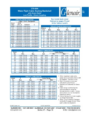
370-004
                          Water-Tight Cable Sealing Backshell
                                        with Strain Relief                                                           37
                                 Low Profile - Direct Coupling


                      TABLE III: FRONT ADAPTER                         See inside back cover
                           J Max - Conn. Designator                   fold-out or pages 13 and
                Shell    A-E-F                                          14 for Tables I and II.
                 Size    J-H-L-S   D-B-G-K      C
                08/09 1.180 (30.0) 1.440 (36.6)                        TABLE IV: ELBOW DIMENSIONS
                10/11 1.180 (30.0) 1.440 (36.6)           Elbow      E           F           G           H
                12/13 1.180 (30.0) 1.440 (36.6)  1.735 (44.1)  Size  Max        Max         Max         Max
                14/15 1.180 (30.0) 1.440 (36.6)  1.915 (48.6)  04  .567 (14.4)  1.187 (30.1)  .636 (16.2) 1.200 (30.5)
                16/17 1.380 (35.0) 1.560 (39.6) 1.915 (48.6)  06  .630 (16.0)  1.250 (31.8)  .710 (18.0) 1.320 (33.5)
                18/19 1.380 (35.0) 1.560 (39.6) 1.915 (48.6)  08  .692 (17.6)  1.312 (33.3)  .731 (18.6) 1.340 (34.0)
                20/21 1.380 (35.0) 1.560 (39.6) 1.915 (48.6)  10  .755 (19.2)  1.655 (42.0)  .825 (21.0) 1.660 (42.2)
                22/23 1.380 (35.0) 1.560 (39.6) 1.915 (48.6)  12  .848 (21.5)  1.765 (44.8)  .988 (25.1) 1.750 (44.5)
                24/25 1.380 (35.0) 1.560 (39.6) 1.915 (48.6)  16  1.036 (26.3)  1.952 (49.6)  1.087 (27.6) 1.925 (48.9)
                28/29 1.610 (40.9) 1.560 (39.6) 1.915 (48.6)  20  1.130 (28.7)  2.098 (53.3)  1.325 (33.7) 2.033 (51.6)
                32/33 1.610 (40.9) 1.750 (44.5) 1.915 (48.6)  24  1.255 (31.9)  2.155 (54.7)  1.337 (34.0) 2.200 (55.9)
                  36  1.610 (40.9) 1.750 (44.5) 1.915 (48.6)  28  1.317 (33.5)  2.250 (57.2)  1.827 (46.4) 2.450 (62.2)
                  40  1.610 (40.9) 2.190 (55.6) 1.915 (48.6)  32  1.348 (34.2)  2.343 (59.5)  2.027 (51.5) 2.450 (62.2)

                                                     TABLE V: CABLE ENTRY
                   Dash         K             L             N                Cable Range              M
                    No.        Max           Max            Ref          Min           Max           Max
                     03    1.219 (31.0)   .812 (20.6)    .135  (3.4)   .156  (4.0)   .219  (5.6)  1.031 (26.2)
                     04    1.219 (31.0)   .937 (23.8)    .203  (5.2)   .188  (4.8)   .312  (7.9)  1.031 (26.2)
                     06    1.219 (31.0)  1.062 (27.0)    .285  (7.2)   .281  (7.1)   .438 (11.1)  1.031 (26.2)
                     08    1.219 (31.0)  1.188 (30.2)    .350  (8.9)   .312  (7.9)   .531 (13.5)  1.031 (26.2)
                     10    1.281 (32.5)  1.312 (33.3)    .390  (9.9)   .375  (9.5)   .625 (15.9)  1.094 (27.8)
                     12    1.281 (32.5)  1.562 (39.7)    .460 (11.7)   .500 (12.7)   .750 (19.1)  1.219 (31.0)
                     16    1.406 (35.7)  1.750 (44.5)    .510 (13.0)   .625 (15.9)   .938 (23.8)  1.219 (31.0)
                     20    1.656 (42.1)  2.250 (57.2)    .695 (17.7)   .938 (23.8)  1.250 (31.8)  1.344 (34.1)
                     24    1.906 (48.4)  2.375 (60.3)    .715 (18.2)  1.000 (25.4)  1.375 (34.9)  1.547 (39.3)
                     28    1.906 (48.4)  2.625 (66.7)    .915 (23.2)  1.250 (31.8)  1.625 (41.3)  1.547 (39.3)
                     32    2.000 (50.8)  2.812 (71.4)   1.070 (27.2)  1.500 (38.1)  1.875 (47.6)  1.734 (44.0)


                                    TABLE VI: CABLE ENTRY                        1. When maximum cable entry
                 Dash       P             R                Cable Range             (page 22) is exceeded, Style 2 will
                  No.      Max           Max            Min           Max          be supplied.  Function S only.
                  03     .739 (18.8)   .812 (20.6)   .156  (4.0)    .219  (5.6)  2. Metric dimensions (mm) are
                  04     .739 (18.8)   .937 (23.8)   .188  (4.8)    .312  (7.9)    indicated in parentheses.
                  06     .739 (18.8)  1.062 (27.0)   .281  (7.1)    .438 (11.1)  3. Saddles are bottomed on Clamp
                  08     .739 (18.8)  1.188 (30.2)   .312  (7.9)    .531 (13.5)    Ears.
                  10     .791 (20.1)  1.312 (33.3)   .375  (9.5)    .625 (15.9)  4. Cable range is defined as the
                  12     .880 (22.4)  1.562 (39.7)   .500 (12.7)    .750 (19.1)    accommodations range for
                  16     .901 (22.9)  1.750 (44.5)   .625 (15.9)    .938 (23.8)    the wire bundle or cable.  Dimen-
                  20    1.031 (26.2)  2.250 (57.2)   .938 (23.8)  1.250 (31.8)     sions shown are not intended for
                  24    1.250 (31.8)  2.375 (60.3)  1.000 (25.4)  1.375 (34.9)     inspection criteria.
                  28    1.250 (31.8)  2.625 (66.7)  1.250 (31.8)  1.625 (41.3)   5. Consult factory for shorter lengths
                  32    1.312 (33.3)  2.812 (71.4)  1.500 (38.1)  1.875 (47.6)     on straight backshells.
                                                                                 6. When using Connector Designa-
                                                                                   tor B refer to pages 18 and 19 for
                                                                                   part number development.

               © 2005 Glenair, Inc.                      CAGE Code 06324                            Printed in U.S.A.
                GLENAIR, INC. • 1211 AIR WAY • GLENDALE, CA 91201-2497 • 818-247-6000 • FAX 818-500-9912
               www.glenair.com                       Series 37 -  Page 19               E-Mail: sales@glenair.com