
Page 232 - Circular Connector Backshells and Accessories
P. 232
380-019
EMI/RFI Non-Environmental Backshell
with Strain Relief
38
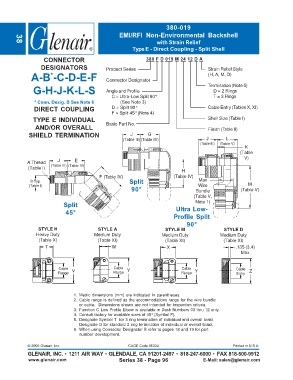
Type E - Direct Coupling - Split Shell
CONNECTOR 380 F D 019 M 24 12 D A
DESIGNATORS Product Series Strain Relief Style
A-B -C-D-E-F Connector Designator (H, A, M, D)
*
G-H-J-K-L-S Angle and Profile Termination (Note 5)
D = 2 Rings
C = Ultra-Low Split 90° T = 3 Rings
* Conn. Desig. B See Note 6 (See Note 3)
DIRECT COUPLING D = Split 90° Cable Entry (Tables X, XI)
F = Split 45° (Note 4)
TYPE E INDIVIDUAL Shell Size (Table I)
AND/OR OVERALL Basic Part No. Finish (Table II)
SHIELD TERMINATION J G
(Table III)(Table IV) J L
(Table III) (Table V)
K
(Table
V)
J E
A Thread
(Table III) (Table IV)
(Table I)
H
F (Table IV) (Table IV)
B Typ. Split Max
(Table I) Wire M
90° Bundle (Table V)
(Table V,
Note 1)
Split Ultra Low-
45°
Profile Split
90°
STYLE H STYLE A STYLE M STYLE D
Heavy Duty Medium Duty Medium Duty Medium Duty
(Table X) (Table XI) (Table XI) (Table XI)
T W X .135 (3.4)
Max
Cable Cable Cable Cable
Range V Range Y Range Y Entry Z
1. Metric dimensions (mm) are indicated in parentheses.
2. Cable range is defined as the accommodations range for the wire bundle
or cable. Dimensions shown are not intended for inspection criteria.
3. Function C Low Profile Elbow is available in Dash Numbers 03 thru 12 only.
4. Consult factory for available sizes of 45° (Symbol F).
5. Designate Symbol T for 3 ring termination of individual and overall braid.
Designate D for standard 2 ring termination of individual or overall braid.
6. When using Connector Designator B refer to pages 18 and 19 for part
number development.
© 2005 Glenair, Inc. CAGE Code 06324 Printed in U.S.A.
GLENAIR, INC. • 1211 AIR WAY • GLENDALE, CA 91201-2497 • 818-247-6000 • FAX 818-500-9912
www.glenair.com Series 38 - Page 96 E-Mail: sales@glenair.com